


Fiber cable management used to be the last item on a build schedule, handled by whichever contractor finished termination first. In 2026 it has moved into the design phase, because the numbers no longer allow it to be an afterthought. A single 51.2T switch populated with 64 OSFP ports at 800G carries 1,024 fibers into one rack unit of panel space. An AI training rack can pull 512 to 1,024 fibers across its rear. Power density has climbed past 100 kW per rack, which means airflow paths that were once forgiving are now the difference between an optical module running at 55°C and one throttling at 70°C.
When fiber counts were in the hundreds per row, a bundle that sagged below its bend radius or a patch cord routed across an intake vent was a cosmetic problem. At today’s density it becomes a link budget problem, a thermal problem, and a service problem that shows up as failed optics three quarters after handover. This guide is written for the people who have to make the specification decisions: which topology, which panel architecture, which trunk strategy, which labeling scheme, and what to reject at acceptance. It is deliberately not an introduction to fiber optics. If you are still choosing between singlemode and multimode, start with our patch cord selection guide and come back.
1. Decide the Topology Before You Buy a Single Panel
Cable management problems are usually born in the topology drawing. Two buildings with identical fiber counts can produce completely different rear-cabinet congestion depending on whether the design uses cross-connects or interconnects, and whether the fabric is patched at the MDA only or again at every EDA.
The structured cabling model defined in ISO/IEC 11801-1 and the data center topology guidance in ANSI/TIA-942 remain the reference framework: a main distribution area, horizontal distribution areas, and equipment distribution areas, connected by backbone and by patching that is intentionally visible and reconfigurable. In AI fabrics, that model is often compressed. Many operators run a two-tier spine-leaf with direct interconnect at the leaf, skipping the cross-connect to save insertion loss and rack space. That is a legitimate decision, but it transfers rearrangement work from a patch field to a technician with a ladder in a live aisle, and it removes the 0.75 dB of loss that two extra connector pairs would have added to the link budget.
| Design choice | Cross-connect at MDA/HDA | Direct interconnect |
|---|---|---|
| Insertion loss | Adds two connector pairs (roughly 0.3 to 0.6 dB per end-to-end link at 850 nm MMF) | Lowest achievable loss, more headroom for 800G/1.6T |
| Rear cabinet congestion | Concentrated at the distribution frame, deliberately engineered with slack storage | Distributed into every leaf and spine cabinet, often in space nobody planned |
| MAC work | Re-patch at the frame, no access to production equipment | Requires access to live switch ports |
| Move/add/change time | 15 to 30 minutes per circuit once labeling is disciplined | 30 to 90 minutes, plus change window |
| Best fit | Multi-tenant, mixed generations, frequent reconfiguration | Single-tenant AI pods with a fixed topology for 3 to 5 years |
For AI pods the pragmatic answer is usually a hybrid: direct interconnect inside the pod where loss and latency matter most, plus one cross-connect field at the pod boundary where the pod meets the spine and where you will actually rearrange things. Sizing that boundary field is covered in detail in our optical distribution frame guide; the point here is that the boundary is where you store slack, and the pod interior is not.
2. Panel Architecture and Port Density: The Real Constraint Is Rear Access
Panel selection is usually framed as a density contest. One rack unit of LC panels with six 24-fiber cassettes holds 144 fibers, which is 72 duplex ports. An MPO-16 based cassette in the same space pushes the fiber count higher per unit but delivers fewer duplex ports per cassette. Choosing between them on density alone produces a panel that fits the rack elevation and then cannot be serviced, because there is no room behind it for a bend-radius-compliant cord to exit.
Four rear-access realities should drive the decision:
- Exiting cord volume. A fully populated 1U, 144-fiber LC panel with 2.0 mm cords has around 450 mm² of cord cross-section before any slack is counted. If the vertical manager beside it has 60 mm of usable depth per side, that bundle will not lie flat, and installers will compress it against the panel. This is the single most common cause of attenuation drift in high-density rows.
- Module service clearance. Rear-mounted cassettes that require the trunk to be disconnected before removal turn a 10-minute module swap into a circuit outage. Front-removable cassette designs cost more per unit and pay for themselves the first time a branch leg fails.
- Connector format trajectory. If the site is planning a move from MPO-12 to MPO-16 for 800G, or toward MMC/VSFF for higher port counts, a fixed-format panel is a stranded asset. Modular chassis that accept interchangeable cassettes let you change format without changing the rack. The density and sequencing trade-offs between formats are set out in our comparison of MMC versus MPO migration and in the earlier analysis of LC to MMC port density.
- Front-side labeling real estate. A panel that relies on tiny port numbers etched at 4 pt is unusable in a live aisle. Plan for a label field per cassette group, not per port, plus a port map that a technician can photograph.
| Panel approach | Typical density (1U) | Best use | Watch out for |
|---|---|---|---|
| Field-terminated LC adapter panel | 72 to 144 fibers | Low-count edge rooms, long singlemode runs, mixed connector types | Pigtail splice trays consume depth; needs skilled termination and testing |
| MPO-12 cassette panel | 96 to 144 fibers | 10G to 400G fabrics with duplex optics, structured MDA/HDA patch fields | Polarity discipline and cassette format lock-in |
| MPO-16 / 400G-800G cassette panel | 128 to 256 fibers | 800G SR8/DR8 and 1.6T fabrics, spine-leaf trunks | Fewer duplex ports per unit; needs MPO-16 test capability |
| MMC / VSFF high-density panel | Up to 432 fibers | New AI builds where rack units are the scarcest resource | Tooling, cleaning and test equipment ecosystem still maturing |
| Modular chassis (swappable cassettes) | Depends on module | Multi-generation sites, staged build-outs | Higher unit cost, module lead time risk |
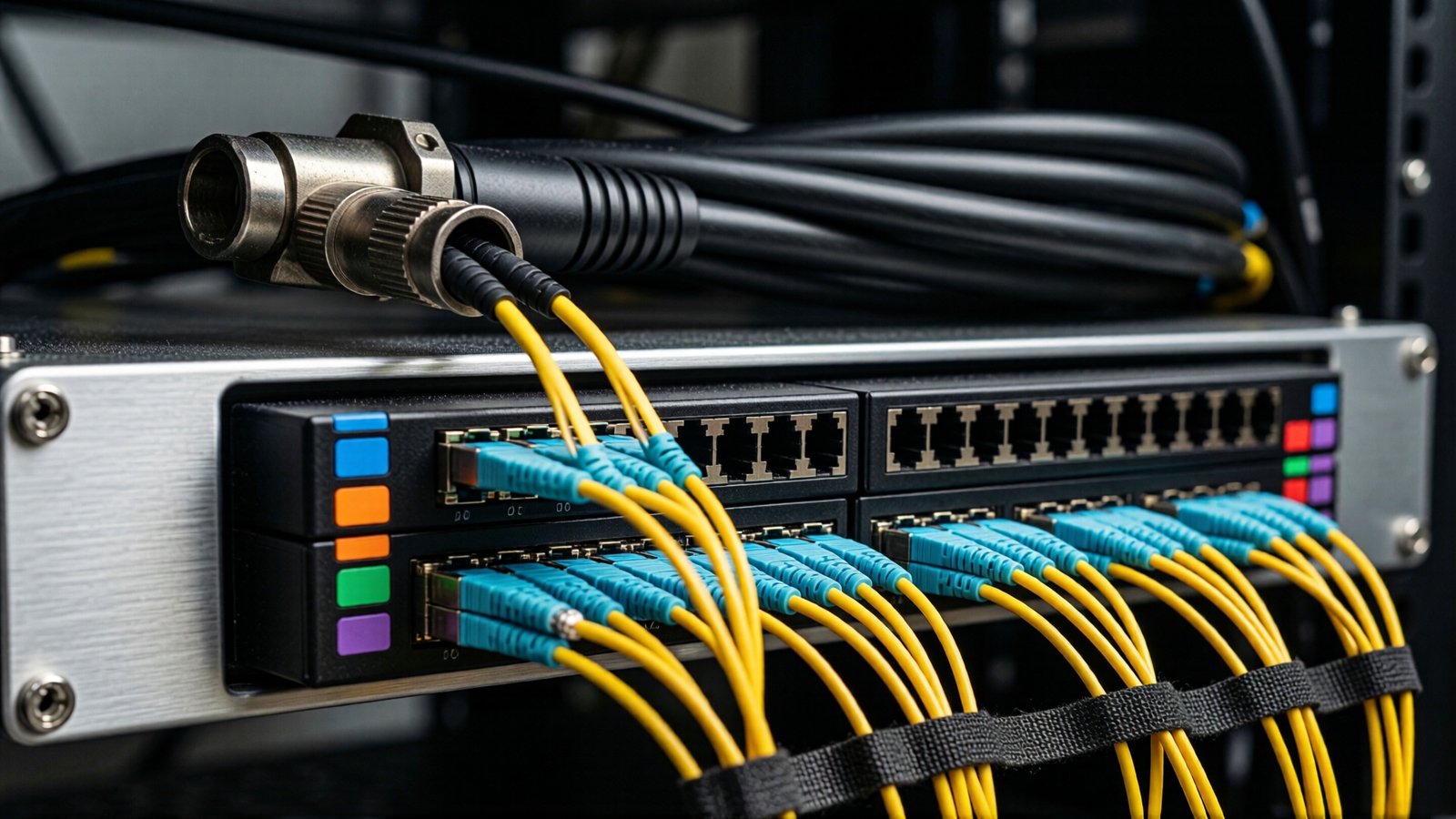
If your build is 400G or above, the cassette format decision is effectively a fabric decision. Our MPO/MTP trunk cable guide works through fiber count and lane mapping, and the 800G interconnect guide covers the port-to-fiber arithmetic per switch.
3. Routing, Bend Radius, and Where Slack Actually Lives
Bend radius is the most quoted and least enforced number in a data center. The working figures are straightforward: for indoor jacketed fiber cords and trunks, keep at least 10 times the cable outer diameter as a static minimum, and 20 times during installation where the cable is under tension. For a 3.0 mm MPO trunk that means 30 mm static and 60 mm during pull; for a 2.0 mm duplex cord, 20 mm static. A 900 µm tight-buffered fiber inside a splice tray is more fragile still and should never see a radius below 15 mm.
What fails in practice is not a single sharp bend but accumulated microbend: cords zip-tied into a tight vertical bundle, then bent 90 degrees at the panel face, then pulled sideways to reach a port three units away. Each of those is within tolerance alone. Together they produce the 1.5 to 3 dB of unexplained loss that field testing attributes to “connector quality”.
| Element | Static minimum radius | Practical design allowance |
|---|---|---|
| 2.0 mm duplex patch cord | 20 mm (10× OD) | 25 mm at panel exit, 40 mm at slack loops |
| 3.0 mm MPO trunk (12F/16F/24F) | 30 mm | 40 mm in tray turns, 75 mm at cable entry |
| Ribbon or 200 µm reduced-coating fiber | Per manufacturer, often 10 mm | 15 mm minimum with rigid routing guides |
| Bend-insensitive singlemode (G.657.A2) | 7.5 mm at 1550 nm | Still design to 15 mm to protect connector boots |
| OFC/basket tray fill | Not a radius issue | Keep below 50% cross-section fill to allow future additions |
Two structural decisions determine whether radius discipline survives operations. First, overhead versus underfloor: overhead basket tray at 2.4 m with drop-down ladders keeps fiber away from liquid cooling piping and power busway, and makes visual inspection possible without moving tiles. Second, vertical manager capacity: size the manager for the final state plus 30 percent, not the initial build. Our notes on vertical and horizontal cable managers cover the finger spacing and door-clearance details that determine whether a technician can actually dress a 144-cord bundle.
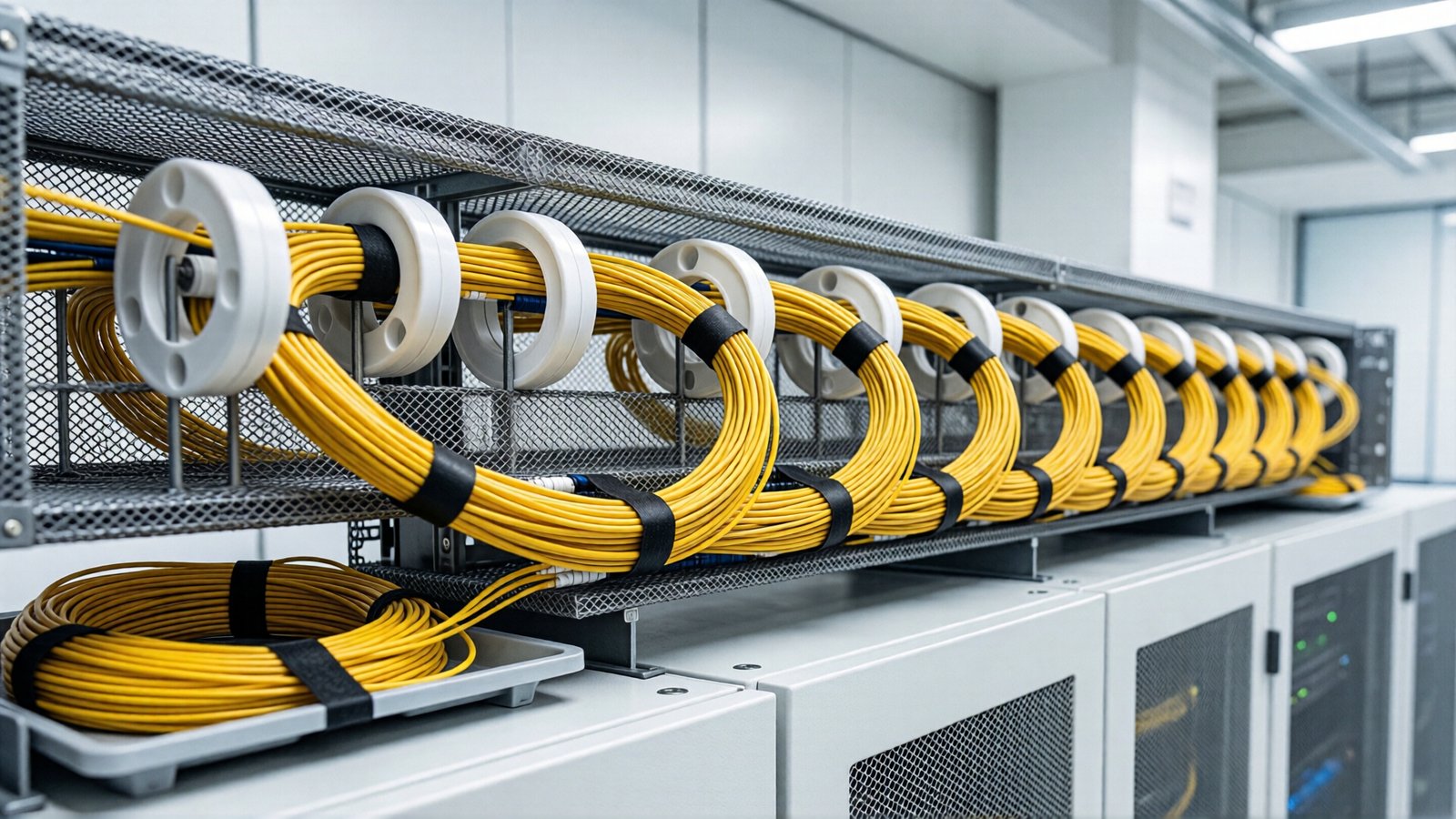
Slack storage deserves its own budget line. Every trunk needs one service loop long enough to reach the farthest port in the panel plus the floor, typically 1.0 to 1.5 m, stored in a tray or a dedicated slack spool, never coiled behind a panel where it will be crushed when the next circuit is added. The routing pattern that keeps slack out of intake airflow is also a thermal decision, and we cover that trade-off in our analysis of how fiber routing shapes 800G/1.6T thermal performance.
4. Polarity and Labeling: The Part Everyone Agrees Is Important and Nobody Funds
Polarity errors are the most expensive category of cabling defect because they pass continuity, pass length, and fail only at the application layer. A single reversed pair inside a 24-fiber trunk can present as a link that trains at 200G instead of 400G, which sends engineers into the optics configuration before anyone checks the patch field.
The Method A, B, and C framework for duplex and array connections remains the standard vocabulary, and our polarity guide covers the pair-flip logic per method. What matters at design time is that the method is chosen once, written into the specification, and enforced at every cassette and trunk in the chain. Mixing a Method B trunk with a Method A cassette is a guaranteed failure that no amount of labeling discipline will catch, because the label describes intent rather than the physical build.
For labeling, a scheme is only worth the discipline behind it. The pattern that survives audits at scale is positional, not descriptive:
[ROOM]-[ROW]-[CABINET]-[U]-[PANEL]-[PORT]
Example: DC1-A12-C03-U18-P2-14
MPO group label: DC1-A12-C03-U18-P2/GRP4 (MPO-16, fibers 49-64, polarity B)
Three rules make this usable. Label the MPO group, not just each LC: a technician tracing a 16-fiber port group needs to see the group identity at a glance. Record the polarity method on the trunk label itself, because the next team will not read the design document. And print from a label printer with a durable adhesive rated for the operating temperature, since handwritten labels fall off at 45°C rear-cabinet temperatures.
Pair the label scheme with a port map that is machine-readable. A spreadsheet that is regenerated at every change is better than a database that nobody updates; a database that is regenerated from an automated test report is better still. The acceptance workflow in section 9 explains how to tie the two together.
5. MPO Trunks and Breakouts: Fewer Cables, More Design Work
Trunking is how high-density builds stay buildable. Instead of pulling 144 individual duplex cords from the MDA to a leaf rack, you pull six 24-fiber MPO trunks and break them out at cassettes. The cable count behind the rack drops by an order of magnitude, pull time drops proportionally, and the rack’s rear becomes inspectable.
The costs are real and should be planned for. Trunking moves complexity into the transition point: every trunk needs a cassette or breakout module, every module adds two connector pairs to the link, and each of those pairs is an opportunity for endface contamination. For 800G links built on MPO-16, the loss budget is tight enough that the difference between a two-cassette path and a three-cassette path matters; our loss budget calculation guide shows where the decibels go.
Practical trunk design rules for 2026 builds:
- Match fiber count to the port group, not the switch. MPO-16 maps cleanly to 8×100G or 8×200G lanes. Buying 24-fiber trunks because they are cheaper per fiber creates breakout waste and polarity confusion at every transition.
- Buy pre-terminated, and buy tested. Factory-terminated trunks with per-end test reports shift the largest labor risk off site. The economics, including lead times, are in our pre-terminated versus field-terminated comparison.
- Plan the breakout location deliberately. Breaking out at the rack entry keeps cassettes accessible; breaking out inside the cabinet saves a unit of rack space and costs a service visit every time a leg fails.
- Keep 10 to 15 percent spare fiber per trunk run. Not for capacity, but because re-termination during a fault often consumes a strand group.
The same body of work applies to tier-1 module choices: whether you standardise on 12-fiber or 16-fiber MPO affects every panel, cassette, and tester you buy for the next five years. If you are still weighing connector families, our MPO vs MTP connector comparison covers the interoperability and tolerance differences that matter at 400G and above.
6. Managing Cable in a High-Density AI Rack
An AI training rack is no longer a networking rack with a few extra links. Between scale-out fabric ports, storage, and in-band management, a GPU rack commonly lands at 256 to 1,024 fibers, and the rear of the cabinet becomes the binding constraint on how fast it can be deployed and repaired.
| Rack role | Typical fiber count | Rear management requirement |
|---|---|---|
| Leaf / ToR in a 400G fabric | 128 to 256 fibers | Two vertical managers, 100 mm usable depth, front-access cassettes |
| Spine in a 51.2T leaf-spine build | 512 to 1,024 fibers | Top-of-rack trunk entry tray plus 150 mm vertical managers on both sides |
| GPU compute rack, 8-way scale-out | 256 to 512 fibers | Segregated fiber and power sides, dedicate one side to optics entirely |
| GPU compute rack, rack-scale system | 512 to 1,024 fibers | Overhead routing to a mid-row distribution point; no rear cord storage |
| Storage / management rack | 64 to 128 fibers | Standard 1U panel and single manager is sufficient |
The arithmetic for your own rack is mechanical and worth doing before the purchase order: multiply switch ports by fibers per port, add 20 percent for management and spares, then compare that number to panel capacity and manager volume. Our strand count calculation guide walks through the calculation for common GPU and switch configurations.
Four layout rules pay for themselves in the first year:
- Segregate by media, not by destination. Fiber on one side, copper and power on the other. Mixed bundles make every re-patch a risk of disturbing a 400G link to reach a 1G management port.
- Route to the panel, not to the port. Cords should reach a defined panel port in a defined pattern. Ad hoc direct-to-port routing is what produces the tangle that makes the next technician remove a live cord.
- Keep cords out of the intake face. A single 2.0 mm bundle across a server intake displaces enough airflow to raise local inlet temperature by 2 to 4°C in a 20 kW rack, and considerably more at 100 kW.
- Leave one unit of rack space per 400 fibers for slack and future transition modules. It is the cheapest insurance in the bill of materials.
7. Liquid Cooling and High-Power Racks: What Changes for Cabling
Once racks pass roughly 30 kW, most builds use direct-to-chip liquid cooling, and once they pass 60 kW, coolant distribution manifolds and quick-disconnects occupy space that used to belong to cabling. That creates three new problems for fiber management.
Physical contention and drip risk. Coolant lines run vertically at the rear of the cabinet, precisely where vertical managers want to sit. The design answer is to assign the rear into zones before the rack elevation is drawn: one side for liquid manifolds and power, one side for fiber, with a physical barrier between them. Never let a fiber bundle sit under a quick-disconnect joint; a slow drip onto a cassette will not destroy the link immediately, it will produce intermittent loss that takes weeks to diagnose. Background on the cooling architecture side is in our liquid-cooled data center trends piece.
Clearance for service. A quick-disconnect coupling needs 100 to 150 mm of straight access to engage and disengage, and that tool path must be kept clear of cords. In practice this means the fiber field is offset from the liquid field by at least 200 mm, or the two are placed on opposite sides of the cabinet.
Thermal shadowing. Dense fiber bundles crossing the rear of a high-power rack restrict the exhaust path. At 100 kW per rack the exhaust temperature at the rear can exceed 45°C, which is close to the upper limit for many cord jackets and cable ties. Use plenum-rated or high-temperature cords where the exhaust path is close, and specify cable ties rated for the environment; nylon ties that soften at 50°C are a known failure mode.
There is also a documentation consequence. When a rack mixes liquid, power, and fiber, the acceptance walkthrough has to cover all three, and the fiber record needs to note which side of the cabinet each trunk enters. Six months later, that entry-side note is what tells a contractor which of two identical cabinets to open.
8. Migration, Expansion, and Brownfield Retrofits
Most cable management projects in 2026 are not greenfield. They are a 400G row being extended with 800G, or a copper-heavy 2015 build being re-populated with optical leaf-spine. Retrofits follow a different discipline than new builds, because every change happens next to live circuits.
Plan the retrofit in three passes. First, survey and record: photograph every panel, capture the port map, and test a sample of existing links to establish a baseline. Second, build the parallel path: install new trunks and panels while the old field still carries traffic, so the cutover is a re-patch rather than a rebuild. Third, cut over in bounded windows, one trunk group at a time, with a documented rollback that does not depend on memory.
Two specific risks deserve attention. Reusing existing trunks is tempting on cost grounds and dangerous on loss grounds, because a trunk pulled through three construction phases may have accumulated microbend damage that only appears at 800G. Test before reuse, and budget replacement for any run that cannot produce a clean per-fiber result. Second, panel space in brownfield cabinets is usually over-committed, so the retrofit needs a staging location: a mid-row distribution frame that takes new trunks and fans out to cabinets that have no free rack units left. That is exactly the role a modular distribution chassis plays, and the design logic behind it is set out in our notes on modular fiber distribution.
9. Acceptance Testing and Ongoing Operations
Acceptance is where cable management is either proven or quietly deferred into operations. The test matrix below is proportionate for a high-density fiber build; scale the sample size down for edge rooms and up for AI pods.
| Check | Method | Acceptance criterion |
|---|---|---|
| Endface cleanliness | Inspection scope at 200× or 400× on 100% of connectors | No scratches in the core zone, no contamination; re-clean and re-inspect until pass |
| Insertion loss, per link | OLTS with reference-grade launch conditions, both directions | Per design budget; typical singlemode duplex ≤ 1.5 dB for two-pair path |
| Per-fiber loss in MPO trunks | MPO tester or OLTS per fiber pair | Every fiber recorded, not just the best 8 of 12 |
| Polarity verification | Continuity map per trunk, compared to design method | Method A/B/C matches specification, no pair inversions |
| Bend radius at panel exit | Visual, at 100% of panels | No cord tighter than 20 mm; no bundle compressed by a manager door |
| Airflow obstruction | Visual plus spot temperature at inlet | No cord crossing an intake face; inlet temperature within design delta |
| Label and record accuracy | 10% random audit against port map | 100% match; any mismatch triggers a full audit |
Endface inspection is the highest-yield item on that list, and the one most often reduced to a visual glance. Our cleaning and inspection guide covers the tools and the pass criteria in detail; the operational point is that a contaminated connector discovered at acceptance costs minutes, and the same connector discovered after a fabric training failure costs a maintenance window.
In operations, three metrics tell you whether the cable management design is working: mean time to repair a fiber fault, the rate of re-work on move/add/change tickets, and the number of links failing intermittently without a documented cause. All three are downstream of decisions made in design. If MTTR is above two hours in a high-density row, the problem is almost never technician skill; it is that the panel, the label, or the slack storage does not allow the fault to be found.
Finally, budget the disposal side. Cords that have been crushed, zip-tied, or run at 45°C for three years should be removed from the spares pool, not reused in the next build. A clean spares inventory of known-good cords, held by length and connector type, is cheaper than a cabinet full of unlabeled salvage.
10. Specification Checklist for a 2026 Build
Use this as the review sheet before the bill of materials is frozen. Every line is a decision someone has to own, and most of them cost less to change now than after the trunks arrive.
| Area | Decision to record |
|---|---|
| Topology | Cross-connect, interconnect, or hybrid; number of patch points per end-to-end link |
| Fiber count | Fibers per port, ports per switch, fibers per rack, plus 20% growth |
| Connector strategy | LC duplex, MPO-12, MPO-16, or MMC; single format per fabric generation |
| Panel architecture | Cassette density, front vs rear removable, modular vs fixed, per-row standard |
| Trunk strategy | Pre-terminated, tested per end, spare fiber percentage, entry side per cabinet |
| Routing | Overhead vs underfloor, tray fill limit, vertical manager size, slack storage location |
| Bend radius | Static minimum per cable type, enforcement method at panel exit |
| Polarity | Method A/B/C per link type, recorded on trunk labels |
| Labeling | Positional scheme, group labels for MPO, printer and label durability spec |
| High-power racks | Rear zoning plan, liquid/cord separation distance, temperature-rated ties and cords |
| Acceptance | Inspection scope, test matrix, record format, audit sample size |
| Operations | Port map owner, update cadence, MTTR target, spares policy |
Closing: The Design Question Behind the Tangle
Every badly managed fiber row has a traceable origin: a panel chosen for density without rear access, a topology that put the patch field where nobody wanted to work, a trunk pulled with a bend that passed installation and failed at 800G, or a label scheme that existed only in a spreadsheet. None of these are craft failures. They are specification failures, and the standards that describe the physical layer, from ANSI/TIA-942 through the IEC 61300 series test methods, are useful precisely because they force those decisions into the open before installation.
If you are planning an AI cluster, a 400G refresh, or an 800G expansion, the practical next step is to size the fiber count and the panel stack together rather than in sequence. Our team works through those calculations with design teams regularly, and the patch panel selection guide is a reasonable place to start the working session, followed by the high-density deployment practices review for the installation side.