

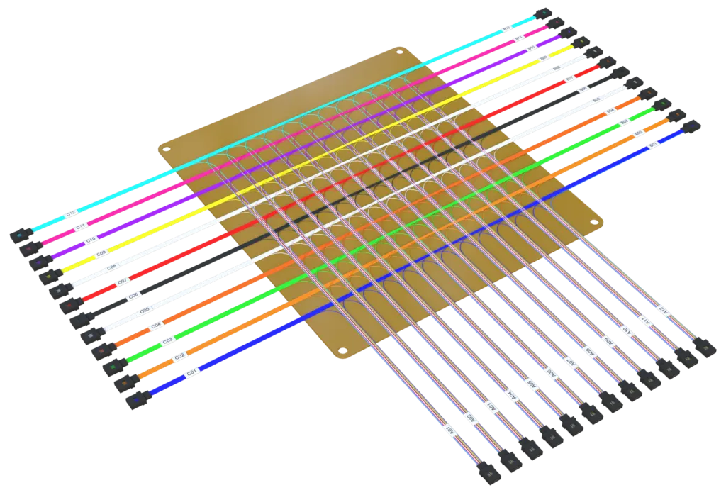
Short answer: Fiber polarity defines how transmit (Tx) and receive (Rx) paths line up end to end across a link. Method A keeps fibers straight through and flips the duplex adapter at the equipment side; Method B uses a crossed patch cord on one end; Method C flips pairs inside a parallel MPO trunk. For modern data center MPO deployments, Method C is the recommended choice because the pair mapping is contained inside a single component.
Why Fiber Polarity Still Decides Whether Your Link Works
Fiber optic polarity is the silent make-or-break factor in every duplex and parallel optical link. Get it wrong and your 400G link lights up nothing — no data, no errors, just a dark module. This guide explains polarity Methods A, B, and C in plain terms, shows which one belongs in your data center, and helps you avoid the most common field mistakes.
What Fiber Polarity Actually Means
Polarity defines the end-to-end alignment of transmit (Tx) and receive (Rx) paths between two transceivers. In a duplex link, position 1 of the transmit side must connect to position 2 of the receive side, and vice versa. In parallel links with 8, 16, or 32 fibers, every channel must land on the correct fiber pair after crossing patch panels, trunks, and cassettes. For an introduction to the connector families involved, see our MPO vs MTP guide.
Method A: Straight-Through, Simple and Predictable
Method A uses a straight-through patch cord at both ends of the link: position 1 connects to position 1, position 2 to position 2. To flip the signal at the equipment side, the duplex adapter at the transceiver uses a Key-Up to Key-Down (A-to-B) orientation. Method A is the most widely deployed in data centers because troubleshooting is intuitive: if both ends use the same polarity, the mapping stays consistent.
Method B: Crossed Pair, One Cable Fits All
Method B uses a crossed patch cord (position 1 to position 2) on the transmit side and a straight cord on the receive side. It requires careful labeling because every connection flips the pair. Method B is common in older telecom plant and in some structured cabling designs where a single cord type was stocked to simplify inventory.
Method C: Pairs Flipped Inside a Parallel Array
Method C flips pairs within a multi-fiber array: pair 1 becomes pair 4, pair 2 becomes pair 3, and so on. It is the recommended approach for MPO-based parallel optics because the flip happens inside the trunk, leaving the breakouts straight and consistent at both ends. Pre-terminated trunk products such as our multi-fiber pre-terminated assemblies are manufactured with the correct Method C mapping, which removes a whole class of field errors.
Which Method Should Your Data Center Use?
| Factor | Method A | Method B | Method C |
|---|---|---|---|
| Typical use | Duplex & parallel, data centers | Legacy telecom, single-cord inventory | MPO parallel optics, 40G/100G/400G |
| Field troubleshooting | Easiest | Moderate, label-dependent | Moderate, pair mapping defined |
| Inventory simplicity | Two cord types | One cord type | One trunk type + straight breakouts |
| Standards alignment | TIA-568, ISO/IEC 11801 | Legacy plants | TIA-568.3, MPO deployments |
Polarity definitions in this guide follow the structured cabling conventions published by the Telecommunications Industry Association (TIA) and the ISO/IEC 11801 cabling standard (ISO), which define the reference models used in Method A, B, and C.
Common Polarity Mistakes We See in the Field
The most frequent errors are mixing Methods A and B in the same channel, using straight cords where crossed cords are required, and forgetting that MPO cassettes flip polarity internally. Always verify with an optical loss tester or a polarity checker before commissioning high-speed links — at 400G and beyond, a single flipped pair can take down the entire port. For a checklist that covers connectors, polish, and polarity together, read our fiber patch cord selection guide.
How ADTEK Simplifies Polarity Management
ADTEK offers MPO trunks, cassettes, and breakout assemblies clearly labeled for Method A and Method C, with color-coded housings and polarity diagrams printed on the packaging. Our pre-terminated trunk solutions reduce field error rates and cut commissioning time, which matters most when every minute of downtime costs revenue. The same design discipline extends across our fiber optic product series, including MPO-ELSFP patch cords for emerging module form factors and high-density fiber array units for precision alignment.
Polarity is only one of the factors that decide whether an AI-scale fabric stays reliable. Our articles on optical interconnect in AI infrastructure and high-density fiber deployment best practices cover the rest of the picture.
Frequently Asked Questions
What is the difference between Method A and Method C polarity?
Method A keeps individual fibers straight through and flips the duplex adapter at the equipment. Method C flips pairs inside a parallel trunk, which is preferred for MPO-based links because the mapping is contained within one component.
Can I mix Method A and Method B in one link?
No. Mixing methods breaks the Tx-to-Rx alignment and the link will not light. Choose one method per channel and document it in your cabling records.
How do I check polarity in an MPO deployment?
Use a polarity checker or an optical loss tester that supports MPO-12/MPO-16 fan-outs. Confirm the pair mapping at the trunk, the cassettes, and the breakouts before connecting transceivers.