

A field perspective on what happens when GPU density meets optical reality
I spent last week reviewing a fiber count estimate for a customer’s NVIDIA NVL72 deployment. I had to check the spreadsheet twice. Then a third time.
The number broke my calculator.
Not because the math was wrong — because the scale of what we’re asking fiber infrastructure to do has quietly crossed a threshold that most rack design playbooks weren’t written for.
The New Math: It’s Not About Servers Anymore
For years, we counted fiber per server. Two 10G links, maybe four. Manageable. Predictable.
AI rack design breaks that model. The relevant unit is no longer the server — it’s the GPU, and the network fabric each GPU needs to participate in training or inference at scale.
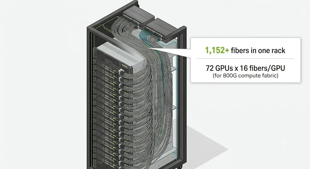
Take the NVIDIA NVL72: 72 GPUs in a single rack. Each GPU needs a compute fabric connection to the network. At 400G, that’s 8 fiber strands per GPU (4 transmit, 4 receive).
72 GPUs × 8 fibers = 576 fibers for compute fabric alone. In one rack.
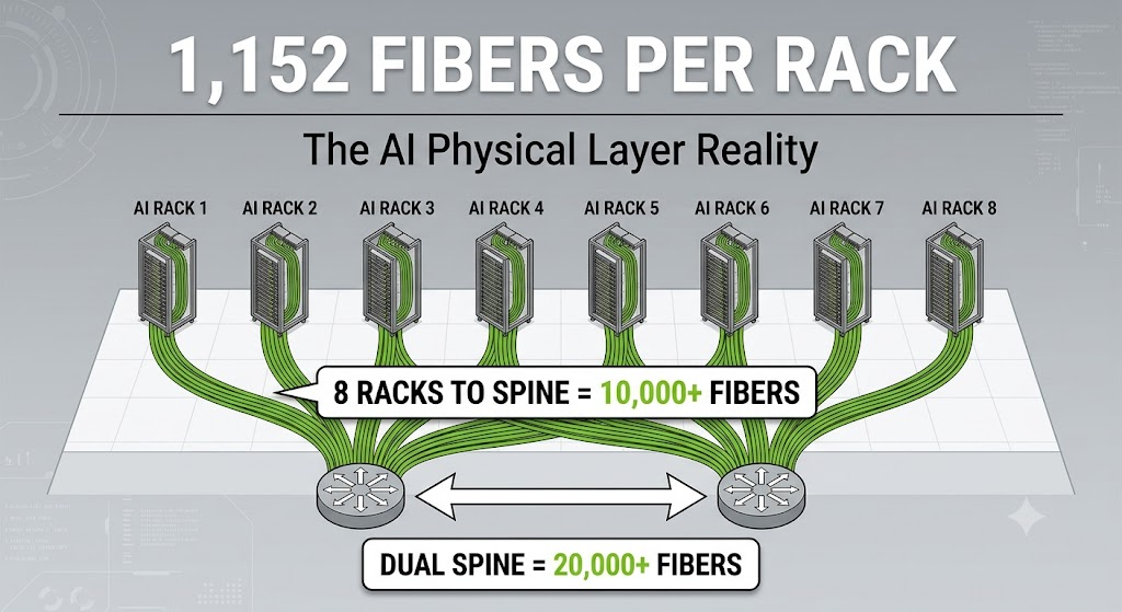
Move to 800G DR8 — 8 lanes of 100G, 16 fibers per GPU — and that becomes 1,152 fibers. Still just compute. Still just one rack.
Add storage fabric (NVMe-oF), management network, and inter-rack spine uplinks, and you’re well past 1,200 strands before you’ve even thought about redundancy or spine aggregation.
When the Core Network Rack Becomes the Bottleneck
Here’s where it gets interesting — and where most early AI designs hit a wall.
Those 1,152 fibers don’t stay in the rack. They converge. If you have eight NVL72 racks feeding into a single spine plane, you’re managing over 10,000 fiber strands at the aggregation layer. Dual spine redundancy doubles that.
To put this in context: a typical data center floor in 2010 ran maybe 1,000 to 2,000 fiber strands total. We’re now talking about that same count inside one rack, and 10× to 20× that at the spine.
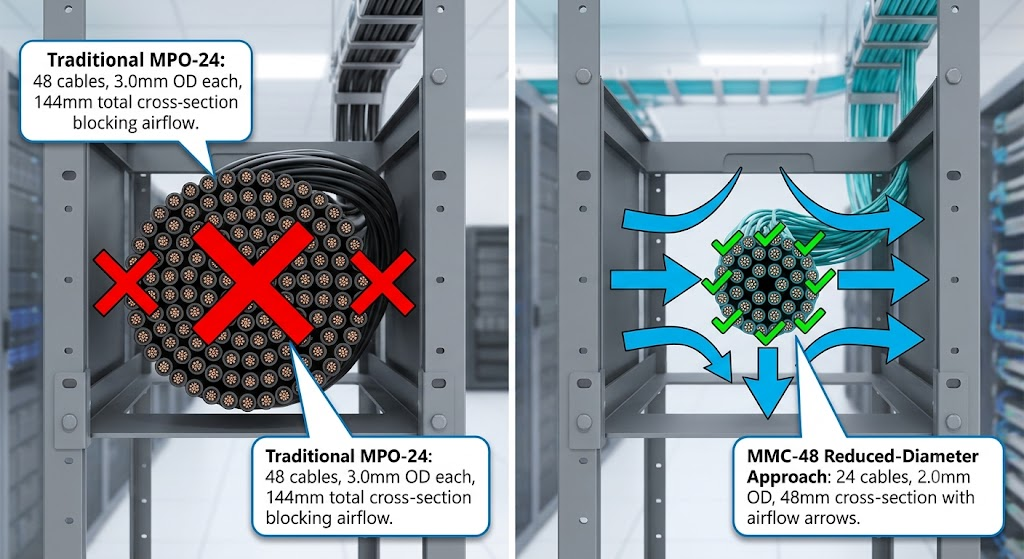
The patch panel becomes the architecture. Not the switch. Not the server. The physical layer — the connectors, the trunk cables, the bend radius, the airflow gap you just filled with a 144mm cable bundle — becomes the constraint that determines whether your $500,000 GPU rack can actually breathe.
Why Connector Choice Is Now a Thermal Decision
This is where the conversation shifts from “which connector has the lowest insertion loss” to “which connector lets me keep the rack cool.”
We’ve seen this firsthand. At current production volumes, we’re terminating over 2 million MMC connectors per month on cable assemblies. The reason isn’t fashion — it’s physics.
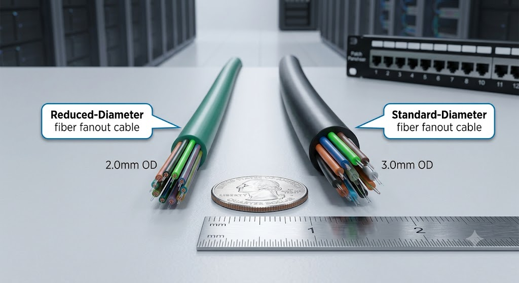
Consider the airflow math. A 1RU panel with 1,152 fibers using traditional MPO-24 trunks means 48 cables at roughly 3.0mm outer diameter each. That’s 144mm of cable cross-section in a 44.45mm tall panel space. The cables don’t just consume port density — they block the perforated panels and air passages that high-wattage AI racks desperately need.
MMC and other VSFF (Very Small Form Factor) connectors change that equation. Same 1,152 fibers, but with higher fiber counts per connector and reduced-diameter fanout cables, you can cut total cable cross-section by roughly two-thirds. The fibers don’t disappear — they just stop acting like a wall in front of your intake.
MPO-16 and MPO-24 remain common requests in the field, and they absolutely have their place in hybrid environments. But when you’re staring at a rack with 1,000+ strands and a 15kW thermal envelope, the connector decision becomes a cooling system decision.
The Base Architecture Question Nobody Asked in 2019
There’s another layer to this that doesn’t get enough attention: base architecture alignment.
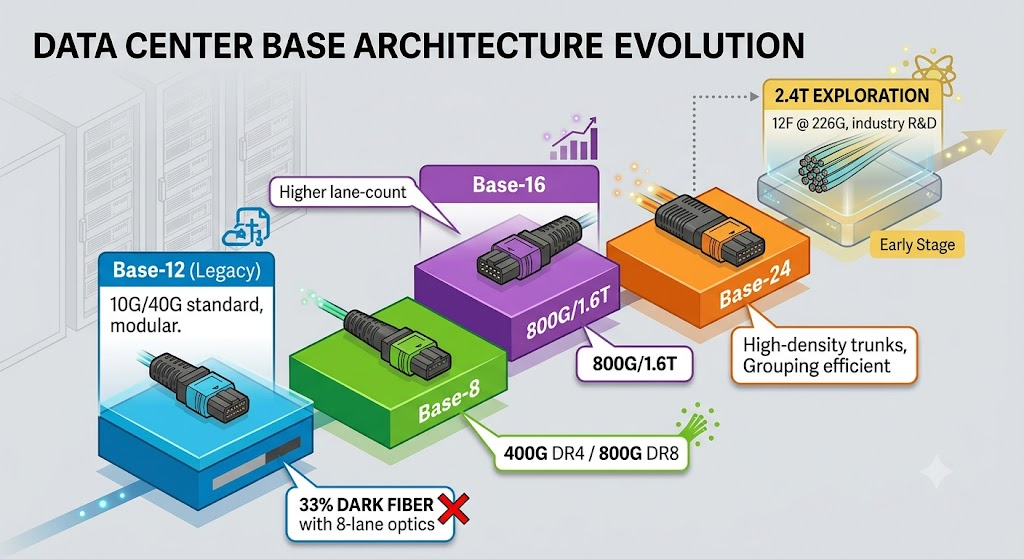
For years, Base-12 dominated data center trunks. It was clean, modular, and worked beautifully for 10G and 40G optics. But 800G and 1.6T optics use 8-lane or 16-lane configurations. Drop a Base-12 trunk into an 8-lane environment, and 33% of your fibers go dark — paid for, patched, and unused.
The field has been moving toward Base-8 for 400G/800G DR configurations, and Base-16 for higher lane-count 1.6T implementations. Base-24 is gaining traction for high-density trunk applications where multiple 8-lane links can be grouped efficiently.
Looking further out, the industry is exploring paths to 2.4T using 12 fibers at approximately 226G per lane — though this remains in early R&D and standardization discussions. The point isn’t to predict which base wins. The point is that your trunk architecture needs to match your lane architecture, or you’re buying stranded capacity by design.
Single-Mode, Full-Stop (With a Footnote)
On the fiber type question: we see the field converging on single-mode (OS2) for AI-scale interconnects, even for intra-rack and intra-row distances that historically defaulted to multimode.
The reason is straightforward. At 800G and beyond, the power budget, reach requirements, and transceiver ecosystem increasingly favor single-mode. Silicon photonics-based transceivers — which most 800G+ designs are moving toward — are inherently single-mode devices.
Multimode (OM4/OM5) still has a role in short-reach legacy environments and specific cost-sensitive deployments. But if you’re designing a rack for a 3-to-5-year lifespan, single-mode is the safer default.
CPO: The Conversation We’re Tracking, Not Predicting
Co-Packaged Optics (CPO) comes up in every AI infrastructure discussion now. The funding behind it is real — NVIDIA, Broadcom, and multiple switch vendors are investing heavily. The concept is compelling: move optics closer to the switch ASIC, reduce power, reduce front-panel pluggable count.
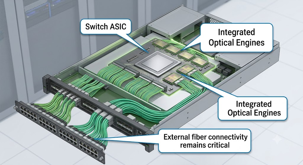
What often gets lost in the CPO conversation is that external fiber connectivity doesn’t go away. It changes location — from the front panel to the mid-board or backplane — but the fiber count, the connector density, and the cable management challenges remain. If anything, CPO may increase the number of short-reach fiber connections inside the rack while reducing the number of pluggable transceivers.
We’re watching this closely. The R&D is serious. But for rack designers making decisions in 2026, CPO is a horizon consideration, not a replacement for the fiber math you need to solve today.
What This Means for Rack Design (Practically)
If you’re designing or specifying AI infrastructure in the next 12 months, three things matter more than they did in 2022:
- Count from the GPU up, not the server down.
The old “2×10G per server” model is irrelevant. Start with GPU count, multiply by fabric links per GPU, multiply by fibers per link. Then add storage, management, and spine aggregation. The number will surprise you. - Treat connector density as a thermal variable.
Every millimeter of cable diameter matters when you’re pushing 15kW+ per rack. Reduced-diameter fanout cables and higher-density connectors aren’t luxury features — they’re thermal survival tools. - Match your trunk base to your lane count.
Base-12 with 8-lane optics is 33% dark fiber. Base-8 or Base-16 aligns with 400G/800G/1.6T lane structures. Base-24 offers grouping efficiency for high-density trunking. The wrong base choice is a structural inefficiencythat compounds at scale.
The Bottom Line
The AI infrastructure conversation is dominated by GPUs, switches, and training frameworks. But the physical layer — the fiber, the connectors, the patch density, the airflow — is where the theoretical meets the operational.
A single NVL72 rack can hold more fiber strands than an entire data center floor from a decade ago. That’s not a footnote. That’s the new baseline.
And it changes how we think about everything from rack depth to cooling strategy to the physical space we allocate for patching.
What’s your experience? If you’ve recently spec’d fiber for an AI rack, did the final strand count match your initial estimate — or did reality exceed the spreadsheet? Curious to hear how others are handling the density math.
This article reflects field observations from active deployments. For infrastructure teams navigating AI rack fiber design, we’re happy to share what we’re seeing across current production environments.