

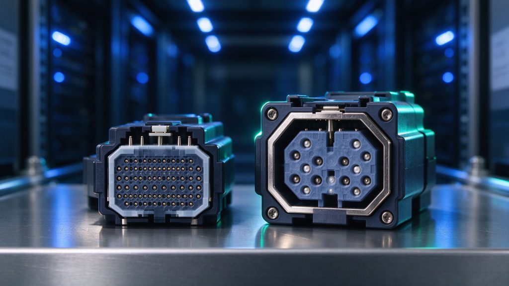
Quick answer: MMC and MPO are both multi-fiber push-on connectors built on an MT-style ferrule, but they are not interchangeable in a rack design. MMC is a Very Small Form Factor (VSFF) connector roughly one third the footprint of an MPO, which lets a 1RU panel carry the same fiber count in far less cable cross-section. MPO remains the wider ecosystem with more cassette, trunk and test-tool support. The practical rule for 2026 AI fabrics: keep MPO where trunks already exist and where 12-fiber or 24-fiber mapping is fixed, use MMC where airflow, front-panel density and cable mass are the binding constraint, and never mix the two inside one polarity domain without documenting the transition point.
This guide is written from the position that most dense fiber problems in AI data centers are mechanical, not optical. The optical budget is usually well understood by the time a rack is ordered. What surprises teams is that a 1RU panel with 1,152 fibers cannot physically accept 48 MPO trunk cables of 3.0 mm diameter without closing the airflow path that the GPU tray depends on. That is the problem MMC exists to solve, and it is the reason the connector decision now sits in the rack architecture discussion rather than in the procurement spreadsheet.
What MMC Changes Compared with MPO
Both connectors use a mechanical transfer (MT) ferrule: a precision plastic block with guide pins that aligns a row of fibers against a matching ferrule. The difference is entirely in the housing, the spring, the boot and the release mechanism — and in how much space those parts consume when a technician plugs eight or forty-eight of them into the same panel.
An MPO connector carries its own latch, a spring that pushes the ferrule forward, a crimp body and a boot. Even the modern short boot MPO occupies a footprint in which roughly one connector per 12.5 mm of panel width is realistic. MMC reduces the housing to a small sliding shell around the ferrule and moves the spring action into the adapter. The result is a connector that fits two MMC ports in the panel width previously needed by one MPO port, with a much shorter boot and a smaller bend envelope behind the panel.
- Footprint: VSFF connectors roughly triple the ports per rack unit compared with MPO, depending on adapter layout.
- Cable mass: round fanout cables become smaller in diameter because the connector body no longer dictates the minimum boot size.
- Airflow: a shorter boot means the cable bundle sits closer to the panel face and blocks less of a perforated front door.
- Serviceability: individual MMC ports can be released without disturbing adjacent connectors, which matters when a single 800G link has to be replaced in a live rack.
What MMC does not change is the ferrule endface geometry, the need for endface inspection, or the polarity rules. Those carry over unchanged from the MPO world, which is why the migration is a mechanical project rather than a new optical discipline.
Why VSFF Exists: The Airflow and Cable Mass Argument
High-density fiber breakage in AI racks is rarely a cleaning problem. It is a thermal problem caused by cable obstruction. A 1RU panel populated with 24-fiber MPO trunks carrying 1,152 fibers means 48 cables entering a 44.45 mm tall opening. At 3.0 mm outer diameter each, that is around 144 mm of cable cross-section competing for a panel opening that is, in most designs, well under half that area once mounting rails and adapter housings are accounted for.
The consequence is predictable: cables bow outward into the cold aisle, the perforated door cannot close flat, and the pressure drop across the rack changes. GPU trays that were validated at a given inlet temperature begin to see a different one. For a rack drawing tens of kilowatts, a few degrees of inlet temperature change is not a cosmetic issue.
VSFF connectors attack the problem from both ends. The connector body shrinks, so the fanout cable can shrink with it. A 16-fiber MMC fanout can be built with a cable jacket substantially smaller than the MPO equivalent, and the bend radius follows the cable diameter. Total cable cross-section in the panel opening can drop by roughly two thirds in a fully converted design, which is the difference between a door that closes and a door that does not.
For the strand-count arithmetic behind these numbers, see our AI rack fiber strand count calculation guide, which works through the GPU-to-fiber multiplication for 400G and 800G fabrics.
Fiber Count, Ferrule Layout and Lane Mapping

MMC is not a single product. It exists in 12-fiber and 16-fiber versions on MT-12 and MT-16 ferrules, and the fiber count determines which optics it can serve.
MPO-12 remains the natural fit for Base-8 and Base-12 trunk architectures: 8 of the 12 positions carry the lanes of a 400G DR4 or a 4×100G breakout, and the remaining 4 positions are either unused or reserved for future use depending on the design. MPO-16 aligns with 8-lane optics such as 800G DR8, where 16 fibers carry 8 transmit and 8 receive lanes in a single connector.
The same logic applies to MMC. An MMC-16 trunk maps to 800G DR8 exactly as an MPO-16 does, and an MMC-12 trunk serves Base-8 or Base-12 architectures. The connector choice does not change the lane mapping; it only changes the physical envelope. What does change is the cassette or breakout you need at the panel, because the adapter interface is not compatible between MMC and MPO.
This matters at the migration boundary. If a rack is half MPO and half MMC, the boundary must be a deliberate panel port, not an improvised hybrid cord. Our MPO MTP trunk cable guide covers the fiber count and lane mapping tables for Base-8, Base-12 and Base-16 in more detail, and the MPO vs MTP connector guide explains why the naming convention itself causes confusion in purchase orders.
Base-8, Base-12 and Base-16 in One Fabric
AI fabrics in 2026 are not built on one base. Compute fabric tends toward Base-8 and Base-16 because 400G and 800G optics use 8 lanes; storage and management traffic may still sit on Base-12 hardware inherited from the 10G and 40G era. A single rack can therefore contain three trunk architectures at once, and each transition between them is a place where polarity errors appear.
The connector decision has to be made per fabric, not per rack. Converting the compute fabric to MMC while leaving storage on MPO is a normal and correct outcome. Converting everything at once is a project that fails on schedule, not on physics.
Polarity: The Part That Breaks During Migration
Polarity is the single most common cause of a link that tests clean but does not pass traffic. In duplex fiber the rule is simple: transmit must reach receive at both ends. In multi-fiber systems the same rule applies lane by lane, and the method used to achieve it — Type A straight, Type B flipped, or Type C pairwise flipped — must be consistent across the entire channel, from transceiver port to transceiver port.
VSFF connectors introduce two new failure modes. First, the adapter keying is smaller and easier to force, so a connector can sometimes be seated in the wrong orientation under poor lighting. Second, because ports are denser, a single reversed trunk in the middle of a 48-port panel is much harder to spot visually. Both are managed with documentation and with a polarity test that checks every lane rather than a sample.
The rules themselves have not changed. Our fiber optic polarity method A B C guide sets out the three methods and the duplex and parallel cases; the migration work is to record which method each channel uses, and to keep the connector transitions inside one method.
A practical rule that saves field time: never place an MMC-to-MPO transition in the middle of a channel unless the transition component is factory-terminated, labeled with its polarity, and tested as a pair. Field-built hybrids are where most polarity and loss surprises originate.
Density, Rack Units and Panel Selection
The point of VSFF is density, but density only pays if the panel supports it. A panel that accepts MMC adapters but has fixed trays and a shallow cable manager will absorb the connector savings and give nothing back. Look for modular panels with independently operating trays, generous front channels and a documented bend radius for the fanout cables actually being used.
Typical configurations in a 1RU modular panel run from 48 to 288 fibers with LC duplex, and considerably higher with multi-fiber cassettes. The limiting factor is usually not the adapter count but the cable management behind it. Our fiber patch panel selection guide walks through the density-versus-manageability trade-off, and the GPX62 extreme high density MMC patch panel shows a production example of a VSFF-based 1RU platform.
When Higher Density Is the Wrong Answer
There is a threshold beyond which density stops helping. If a rack will be reconfigured more than twice a year, an ultra-dense panel increases the risk of disturbing live links during moves, adds and changes. In those racks, a slightly lower density with better front access usually produces fewer outages than a maximally dense panel. Density is a design target, not a design goal.
Optical Performance and Loss Budget
From an optical standpoint, MMC and MPO are close enough that the connector choice rarely drives the link budget. Both use MT ferrules with polished endfaces, both are available in low-loss grades, and both contribute a mated-pair insertion loss in the same range when specified to the same grade. What changes the budget is the number of mated pairs a design introduces.
A conversion that adds an MMC-to-MPO transition introduces two extra mated interfaces per channel. On a 40 km single-mode link that may be irrelevant; on an 800G parallel link with a receiver sensitivity margin measured in fractions of a decibel, two extra pairs can consume the entire design margin. This is why conversion should happen at the panel, where the transition is located within a structured-cabling channel, and not as a mid-span adapter cord.
Run the arithmetic before committing. Our optical loss budget calculation guide gives the formula, typical values, and a worked 40 km example, and the same connector-pair counting method applies to VSFF channels. The 800G optical module selection guide covers the reach classes and power budgets that set the available margin in the first place.
Endface Quality Still Dominates
Contamination remains the leading cause of field failures in multi-fiber links, and VSFF does not change that. Smaller connectors mean smaller endfaces to inspect, which makes a proper inspection scope more important, not less. Every MMC and MPO endface should be inspected and cleaned before the first mating, and inspected again after any reconfiguration. A factory-terminated, pre-inspected assembly is the cheapest insurance available in a high-density rack.
A Migration Plan That Does Not Stall

Converting a live AI fabric from MPO to MMC is best handled as a phased program with a fixed boundary at each step.
- Phase 1 — Inventory. Record every trunk by base, fiber count, polarity method, connector type and length. Without this, the migration cannot be designed.
- Phase 2 — Pick one fabric. Start with the compute fabric, which has the highest density pressure and the most standardized lane mapping.
- Phase 3 — Replace panels first. The panel is the conversion boundary. Changing the panel gives the rack immediate airflow and density benefit without touching transceivers.
- Phase 4 — Convert trunks by bundle. Replace trunk bundles one at a time, retest polarity and loss per channel, and update documentation before the next bundle.
- Phase 5 — Retire MPO only when the boundary is empty. Keeping a documented MPO island is normal and cheaper than a rushed full conversion.
Two scheduling constraints dominate. The first is lead time: pre-terminated VSFF assemblies are built to order and are not stocked in every length and fiber count. The second is labor: each converted bundle needs inspection, cleaning, polarity verification and a loss test, which is a per-port cost rather than a per-panel cost. Our pre-terminated vs field-terminated cabling comparison puts numbers on both, including the point at which factory termination wins on total installed cost.
Standards and Interoperability
MPO and MT ferrules are standardized in the IEC 61754-7 series, and multi-fiber performance is specified through IEC and TIA test procedures. VSFF connectors follow the same ferrule standards but their housings and adapters are, at the time of writing, largely defined by supplier specifications with multi-source agreements still maturing. That has a practical consequence: specify MMC by reference to the adapter, the ferrule grade and the tested endface, not by a generic three-letter name, and require an interoperability statement from the supplier.
Useful references when writing a specification:
- IEC 61754-7 — fiber optic connector interfaces for multi-fiber push-on connectors.
- IEC 61300 series — test and measurement procedures for connector performance.
- TIA TIA-568 and TIA-606 — structured cabling and administration, including polarity documentation.
- IEEE 802.3 — the 400G and 800G Ethernet specifications that define the lane counts the connector must carry.
- OIF implementation agreements — common electrical and optical interface baselines for 400G, 800G and 1.6T modules.
Our own connector documentation sits alongside the MPO vs MTP patch cord guide and the fiber patch cord selection guide, which cover the duplex and breakout side of the same design problem.
Frequently Asked Questions
Is MMC backward compatible with MPO adapters? No. The housing and adapter interfaces are different. An MMC connector will not mate with an MPO adapter, and an MPO connector will not fit an MMC port. Conversion requires a panel port, a cassette or a factory assembly designed for the purpose.
Does MMC reduce insertion loss? Not inherently. Loss is set by ferrule geometry, polish quality, fiber alignment and cleanliness. MMC’s advantage is mechanical: less space, less cable mass and less airflow obstruction for the same fiber count.
Can I use MMC on 400G links? Yes, where the lane mapping fits. A 400G DR4 uses 8 fibers and maps to an MMC-12 trunk in the same way it maps to an MPO-12 trunk. Confirm the cassette or breakout supports the connector you are specifying.
What about 1.6T? 1.6T optics with 16 lanes double the fiber count per link compared with 800G, which is exactly the regime where VSFF density matters most. Plan panel port counts and cable management for 1.6T from the start rather than retrofitting later.
Should I convert an existing rack at all? Only if airflow, cable mass or front-panel space is already a problem, or if the rack is being rebuilt for 800G or 1.6T. A working MPO rack with adequate cooling does not need conversion for its own sake.
Summary
MMC and MPO are the same optical idea in two mechanical envelopes. The choice is driven by rack physics — airflow, cable cross-section, service access — and by the maturity of the ecosystem around each connector, not by optical performance. Convert at the panel, keep polarity inside one method per channel, count every added mated pair in the loss budget, and stage the programme so that a documented MPO island remains acceptable at every step. For the adjacent decisions in the same rack, read the 800G optical interconnect guide and the LPO deployment guide together with this one; they share the same physical layer assumptions.
Before committing to a connector transition, it helps to fix the six upstream gates: interface, connector grade, core count, polarity, loss budget, and cabling format. Our MTP/MPO fiber solutions guide for AI data centers covers each one, and shows where VSFF migration changes the answer.