

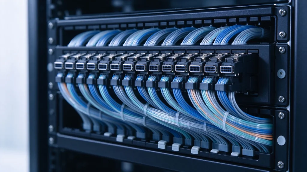
Short answer: An MPO MTP trunk cable is a factory-terminated multi-fiber assembly that carries 8 to 144 fibers between patch panels in a single pre-connectorized run, replacing field splicing and individual jumper pulls in the data center backbone. Choosing one correctly comes down to four decisions: fiber count and connector lane mapping, the polarity method used across the whole channel, the loss budget including every mated pair, and whether the trunk terminates into panels, cassettes, or a direct breakout. Getting polarity or lane mapping wrong at the design stage produces a backbone that lights but will not pass traffic.
What an MPO MTP Trunk Cable Is and Where It Fits
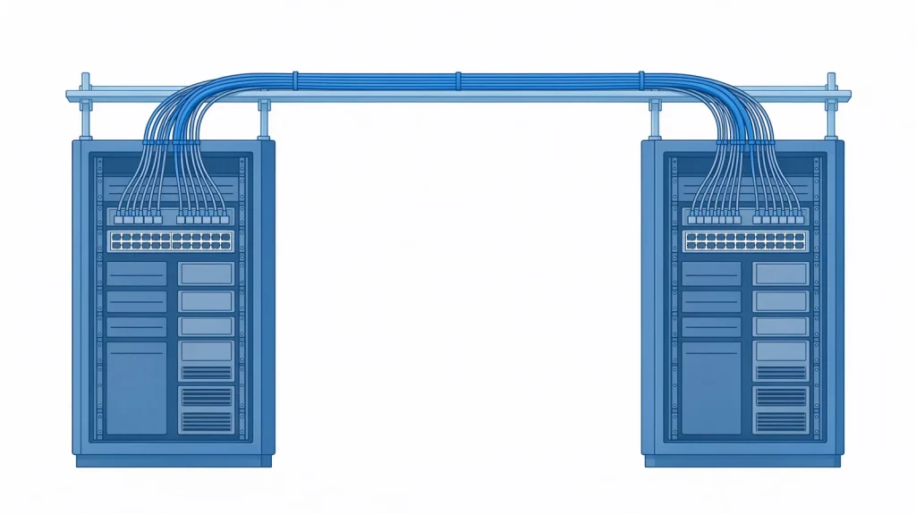
A trunk cable is the long, fixed run in a structured cabling system. In a fiber data center it connects the main distribution area to horizontal distribution areas, or connects row-level patch panels to each other. The assembly is built in a factory with polished multi-fiber connectors on both ends, tested for insertion loss and return loss, and delivered to length so that no splicing is required on site.
The distinction between MPO and MTP matters less at the assembly level than at the component level. MPO is the connector standard; MTP is a licensed, improved implementation of that connector with a removable housing that allows re-work and tighter tolerances. Both mate with each other. The practical differences are explained in MPO vs MTP patch cords, and the connector-level comparison including ferrule and spring design is in the MPO vs MTP connector guide.
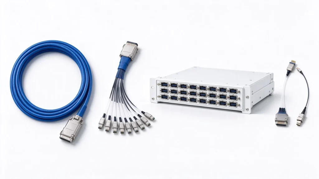
The trunk sits between two other layers. At the equipment end, short patch cords and breakout assemblies connect ports to panels. At the far end, panels or cassettes present the trunk’s fibers as individual or duplex ports. ADTEK supplies both ends of that chain, including trunk fiber patch cords and MTP-to-MTP assemblies such as the MTP female-to-female trunk patch cord.

Fiber Count and Lane Mapping: The First Decision
Trunk fiber count is driven by the port count at both ends, the breakout ratio, and redundancy. Common configurations are 12, 24, 48, 72, 96, and 144 fibers. A useful rule is to size the trunk for the panel’s full capacity rather than for the initial port count, because replacing a trunk later costs far more than installing the higher count at build time.
Lane mapping is the part that causes the most field errors. A 400G port may consume 8 fibers, a 800G port 16, and a breakout cassette may split a 24-fiber trunk into three 8-fiber groups. If the trunk’s fiber ordering does not match the cassette’s internal mapping, positions 1 through 12 at one end will not land where the design expects at the other. Always request the fiber position map from the assembly supplier and verify it against the cassette documentation before placing the order.
Rack-level fiber count planning, including how oversubscription changes strand demand, is covered in how many fiber strands an AI rack needs.
Polarity: Method A, B, and C Across a Full Channel
Polarity defines which transmit position connects to which receive position. Three methods are in common use: Method A (straight through, key-up to key-down), Method B (crossover, key-up to key-down with reversed fiber order), and Method C (pairwise flipped). Method B is the usual choice for parallel optics, where a multi-fiber link must map transmit lanes directly onto receive lanes at the opposite end.
The failure mode to guard against is mixing methods inside one channel. A Method B trunk terminated into a Method A cassette, or a panel that silently flips a pair, produces a channel where some lanes work and others do not. Because parallel links negotiate as a whole, the result is a port that never comes up, or one that comes up and immediately reports errors.
Document the method on the cable schedule and on the panel label, then verify with a polarity tester on a sample channel per row rather than assuming the drawings were followed. The full explanation of each method is in the fiber polarity guide for methods A, B, and C.

Loss Budget for a Trunk-Based Backbone
A trunk-based channel accumulates loss at every interface: the equipment patch cord to panel, the panel to trunk, the trunk to far panel, and the far panel to the destination patch cord. A typical row-to-row trunk channel therefore has four to six mated pairs, not two. Each mated MPO pair contributes its own insertion loss, and a cassette adds internal loss on top.
Build the budget from the transceiver’s available budget downward, subtracting fiber attenuation, connector loss per mated pair, cassette internal loss, and a maintenance margin. Multimode trunks in short runs are dominated by connector and cassette loss; single-mode trunks across a building are dominated by fiber attenuation. The calculation method with reference values is in the optical loss budget calculation guide, and the physics of excess loss is covered in fiber optic attenuation causes and measurement.
Installation Rules That Prevent Damage and Rework
Trunk assemblies are the most expensive single cabling item in a data center build and the easiest to damage during installation. Four rules cover most of the risk:
- Pull by the cable, never by the connector. Use a pulling grip rated for the assembly and keep the tension below the manufacturer’s limit.
- Respect minimum bend radius under load. A trunk pulled around a tight corner at the panel entry point is the most common cause of hidden attenuation increase.
- Keep dust caps on until the moment of mating. A trunk pulled through a construction zone without caps will need every endface cleaned and inspected before use.
- Inspect and clean every endface before first mate and after any re-mate. Multi-fiber connectors present 12 to 24 endfaces at once, and one contaminated fiber degrades one lane while the link stays up.
Handling details specific to multi-fiber jumpers, including connector orientation and torque, are in the MPO/MTP fiber optic jumper installation tips. The inspection acceptance criteria and cleaning workflow are in the fiber endface cleaning and inspection guide.
Trunk Termination Options: Panels, Cassettes, and Breakouts
A trunk rarely terminates directly into equipment. The three common termination patterns are:
Patch panel with MPO adapters. The trunk lands on a panel and remains a parallel link end to end. This is the simplest and lowest-loss option, and it preserves the ability to re-purpose lanes later.
Cassette-based panel. The trunk lands on a cassette that breaks the parallel link into duplex ports, typically LC or MDC. Cassettes add internal loss and impose their own polarity behaviour, so the cassette must be specified together with the trunk rather than separately.
Direct breakout assembly. The trunk ends in fanout legs that connect straight to equipment ports. This removes two mated pairs and their loss, at the cost of flexibility, since the breakout length and fiber count are fixed at order time.
What changes when the module stops retiming. A trunk loss budget assumes a module that can absorb a small shortfall. With linear pluggable optics there is no DSP to do that, so the same assembly has to be measured per lane at commissioning. The acceptance rules are collected in the LPO deployment guide 2026.
Panel selection criteria, including port density and cable management, are covered in how to choose a fiber patch panel. For high-density spine and shuffle applications, the GPX78 1RU inline shuffle panel shows how a fixed shuffle mapping can be built into a panel instead of a custom harness.
Testing and Acceptance
Acceptance testing for a trunk-based backbone is normally a per-fiber insertion loss measurement in both directions at the operating wavelength, compared against the calculated budget rather than against a generic limit. Two additional checks catch the errors that loss testing misses: a polarity verification on a sample channel per row, and an endface inspection record for every connector.
Record the results per fiber position, not per cable. When a lane later reports errors, the test record tells you immediately whether that position was marginal at acceptance or has degraded since.
Frequently Asked Questions About MPO MTP Trunk Cables
What is the difference between an MPO trunk cable and an MTP trunk cable?
Both are multi-fiber assemblies using the MPO connector interface. MTP is a licensed connector design that improves on the generic MPO with a removable housing and tighter mechanical tolerances, which makes re-work and polishing more controllable. They mate with each other, and mixing them in one channel is acceptable as long as the polarity and fiber mapping are correct.
How do I choose between 12-fiber and 24-fiber trunk assemblies?
Base the choice on the port lane count and the breakout pattern. 12-fiber assemblies map cleanly to 40G and 100G parallel links and to duplex breakouts in groups of six. 24-fiber assemblies suit higher-density panels and 400G breakouts. If the panel has 24-fiber adapters, use 24-fiber trunks to avoid leaving half of every adapter unused.
Can I change polarity in the field?
Only if the assembly is designed for it. Some trunks allow the housing to be rotated to switch between Method A and Method B, but many do not. Decide the method at design time, document it, and specify assemblies that match, rather than planning to fix polarity during commissioning.
Why does a trunk channel pass loss testing but fail to link at 400G?
Loss testing measures attenuation, not lane mapping or polarity. A channel with a reversed pair or a mismatched cassette can measure within budget on every fiber and still fail to negotiate, because the transmit lanes do not land on the receive lanes. Verify polarity and fiber position mapping separately from loss.
How often should trunk connectors be inspected after installation?
At acceptance, after any maintenance activity that involves un-mating, and whenever a port reports errors or fails to link. Continuous schedules are unnecessary; event-driven inspection with recorded results is both cheaper and more useful, because it produces a baseline for comparison.
Standards and Reference Material
Multi-fiber connector interfaces are standardized in IEC 61754-7. Structured cabling practices for data centers are published by TIA. Ethernet physical layer specifications relevant to the port types served by these trunks are maintained by IEEE 802.3.
Once trunk construction, polarity, and pulling tension are settled, the remaining decision is the connector and fiber specification itself. Our MTP/MPO fiber solutions selection framework for AI data centers works through interface, connector grade, core count, and loss budget in that order, which is the sequence most trunk projects actually need.