

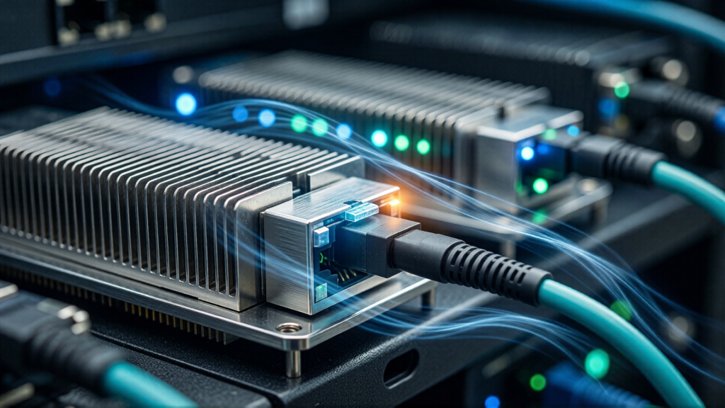
Most thermal discussions about 800G and 1.6T optics stop at the module. Teams compare case-temperature limits, argue about heatsink fin density, and debate whether a given switch can carry a full load of OSFP or QSFP-DD cages at 40 °C inlet. All of that matters. But in a real rack, the component that most often decides whether those modules run cool or run hot is not inside the module at all — it is the bundle of fiber sitting in front of it.
This is the coupling problem that high-density AI fabrics have exposed. A 1 RU switch built for 32×800G has to do two things simultaneously with the same 44 mm of front-panel real estate: pull enough cold air across roughly 400–500 W of optics, and terminate 512 or more individual fibers in a space where a technician still has to reach the latches. Every patch cord you add is both an optical path and an aerodynamic obstruction. Every tidy coil is both a strain-relief measure and a potential heat trap. The two requirements are not independent, and treating them as separate workstreams is how racks end up with modules running 12 °C above their thermal design point while every datasheet in the project folder says the design is fine.
This guide looks at the problem from the cabling side: how fiber mass consumes the airflow budget, how bend radius and retention affect a module’s actual thermal resistance, why case temperature shows up as bit errors before it shows up as an alarm, and how the rules change once liquid cooling takes over the ASIC but leaves the optics in the air path. It is written for engineers specifying optical interconnect for AI clusters, and for the technicians who have to make the design survive contact with a live rack.
Why 800G and 1.6T Optics Turn Heat Into a Cabling Problem
Two curves have been moving in the same direction for several generations, and they reinforce each other. The first is power per port. The second is fiber count per port. Neither is new, but at 800G and 1.6T the product of the two crosses a threshold where the physical layout of cabling starts to dominate thermal outcomes.
On the electrical side, 800G is typically implemented as eight 100G PAM4 lanes, and 1.6T as eight 200G lanes. Each lane generation buys bandwidth by pushing more symbol rate and more amplitude levels through the same package, and the DSP that equalizes those lanes is now a meaningful heat source in its own right. The result is a module whose power dissipation is no longer a rounding error in the rack thermal budget:
| Generation | Typical form factor | Approximate module power | Fibers per link | Optics heat at 32 ports per 1 RU |
|---|---|---|---|---|
| 100G | QSFP28 | ~3.5 W | 2 (Duplex LC) or 8 (MPO) | ~110 W |
| 200G | QSFP56 | ~5–7 W | 8 (MPO-12) | ~200 W |
| 400G | QSFP-DD / OSFP | ~10–14 W | 8 or 16 (MPO-12/16) | ~380 W |
| 800G | OSFP / QSFP-DD800 | ~14–17 W | 16 (2×MPO-12 or MPO-16) | ~500 W |
| 1.6T | OSFP1600 | ~25–32 W | 32 (2×MPO-16 or 4×MPO-12) | ~900 W |
Values are design-planning approximations for 500 m to 2 km reach optics at case temperature, not vendor specifications. Always size the thermal budget from the actual module datasheet and the switch vendor’s port-population derating table.
Read the last two columns together. A fully populated 1.6T chassis puts close to a kilowatt of heat into the front plane of a single rack unit — and it does so in the one location where the airflow has the least room to work: the intake face, before the air has passed a fan, a heatsink, or a baffle. Front-to-back switches are designed on the assumption that cold aisle air arrives at the faceplate at a known velocity and a known temperature. Cable mass in front of the faceplate changes both.
The fiber count is the second half of the problem. An 800G DR8-style link needs 16 fibers; a 1.6T link needs 32. Multiply by 32 ports and a single 1 RU switch can terminate 512–1024 fibers — a strand count that once described an entire hall, as we worked through in the fiber math behind single-rack strand counts. There is no longer a cable-management accessory that can absorb that volume invisibly. Structured approaches — trunking to a high-density panel and breaking out close to the switch — are the standard answer, and the design logic behind them is covered in our optical connectivity specification guide for AI data centers. What that guide does not cover, and what this article addresses, is the thermal consequence of where you put the breakout.
The Airflow Budget: How Cable Mass Quietly Consumes It
A switch chassis is a fan curve intersected with a system impedance curve. That intersection is the operating point, and it determines the actual volumetric flow through the box at a given altitude, inlet temperature, and filter condition. Everything in the air path contributes to the impedance: faceplate perforations, cage fins, heatsink channels, power supply blockage, rear exhaust grilles. The design point assumes those contributions are what the thermal engineer modeled.
Cable mass in front of the faceplate is an impedance term the thermal engineer usually did not model, because at the time the chassis was validated there was no cabling plan. It is applied afterwards, by operations, and it is applied in the worst possible place — immediately upstream of the most temperature-sensitive components in the system.
Faceplate blockage is a pressure-drop problem, not a cosmetic one
A single MPO or MMC jumper is aerodynamically trivial. Two hundred of them, dressed against the bottom two-thirds of a faceplate, are not. What forms is a porous plug: a region where the effective open area drops and the flow has to accelerate through the remaining gaps, with a corresponding rise in local pressure drop. The fan curve does not change, so the system operating point shifts toward lower flow and higher static pressure. Every port in the chassis then sees less cold air, not just the ports behind the bundle.
This is why the thermal symptom is often misattributed. The alarms appear on modules in the middle of the row, far from where the cables actually are, and the instinct is to blame a single bad optic. In practice the whole row has drifted upward, and the mean case temperature — not the maximum — is the number worth watching after a cabling change.
The open-slot error: how one empty cage starves its neighbours
A related failure mode costs nothing to prevent and is extremely common in partially populated switches. An empty cage is a hole. Air, being lazy, takes the path of least resistance straight through the empty slot instead of turning through the fin channels of the adjacent populated cages. The populated modules on either side see a lower local velocity and a higher case temperature than the thermal model predicts. The fix is a port plug or blank in every unused cage, which is a five-second action during installation and a recurring audit item afterwards.
The same logic applies at rack level. Blanking panels in unused rack units are not housekeeping; they preserve the cold-aisle/hot-aisle pressure boundary. A rack with open U spaces and missing blanks is a rack where the inlet temperature at the top of the cabinet is not the temperature the CRAC is delivering.
Why smaller cable did not solve the density paradox
Very-small-form-factor connector families — MMC and MDC style, alongside the MPO/MTP ecosystem — were adopted partly on the promise of relieving front-panel congestion. Per cable, that promise is real: a smaller ferrule and a smaller jacket reduce both the bend envelope and the frontal area. Total cable cross-section, however, scales as count × area, and the count is growing faster than the area is shrinking. A 30 % reduction in diameter cuts area by roughly half, but the migration from one MPO-12 per 400G link to two MPO-12 or MPO-16 per 800G link more than doubles the connector count. The net effect in a fully populated 800G row is usually neutral to negative, which is why the migration path deserves its own analysis — we covered the trade-offs in detail in the MMC vs MPO VSFF connector migration guide.
The practical conclusion for thermal design is uncomfortable but simple: you cannot buy your way out of faceplate blockage by shrinking connectors. You have to change where the cables are, not just how big they are.
Bend Radius, Coiling, and the Hidden Cost of “Neat” Routing
Bend radius is normally treated as a purely optical constraint: exceed the manufacturer’s minimum and you get macrobend loss, which shows up as insertion loss on the test report and as reduced margin at the receiver. That is correct, and it is also the least interesting part of the story. The same geometric decisions that protect the fiber’s optical performance have thermal consequences, and in dense racks the two constraints can genuinely conflict.
Installed bend radius for indoor tight-buffered and riser-rated cables is conventionally held to ten times the cable outer diameter, with a larger allowance during pulling; bend-insensitive fiber designs are often rated lower for installed condition. Those figures are the floor, not the target. The reason to route well above the minimum is not cosmetic: a cable resting at exactly the minimum radius, under tension, at elevated temperature, is a cable whose long-term loss will drift. The cable datasheet governs — but the cable datasheet assumes the cable is not also being asked to hold its own weight in a vertical run behind a door.
The coil that insulates the thing it is supposed to protect
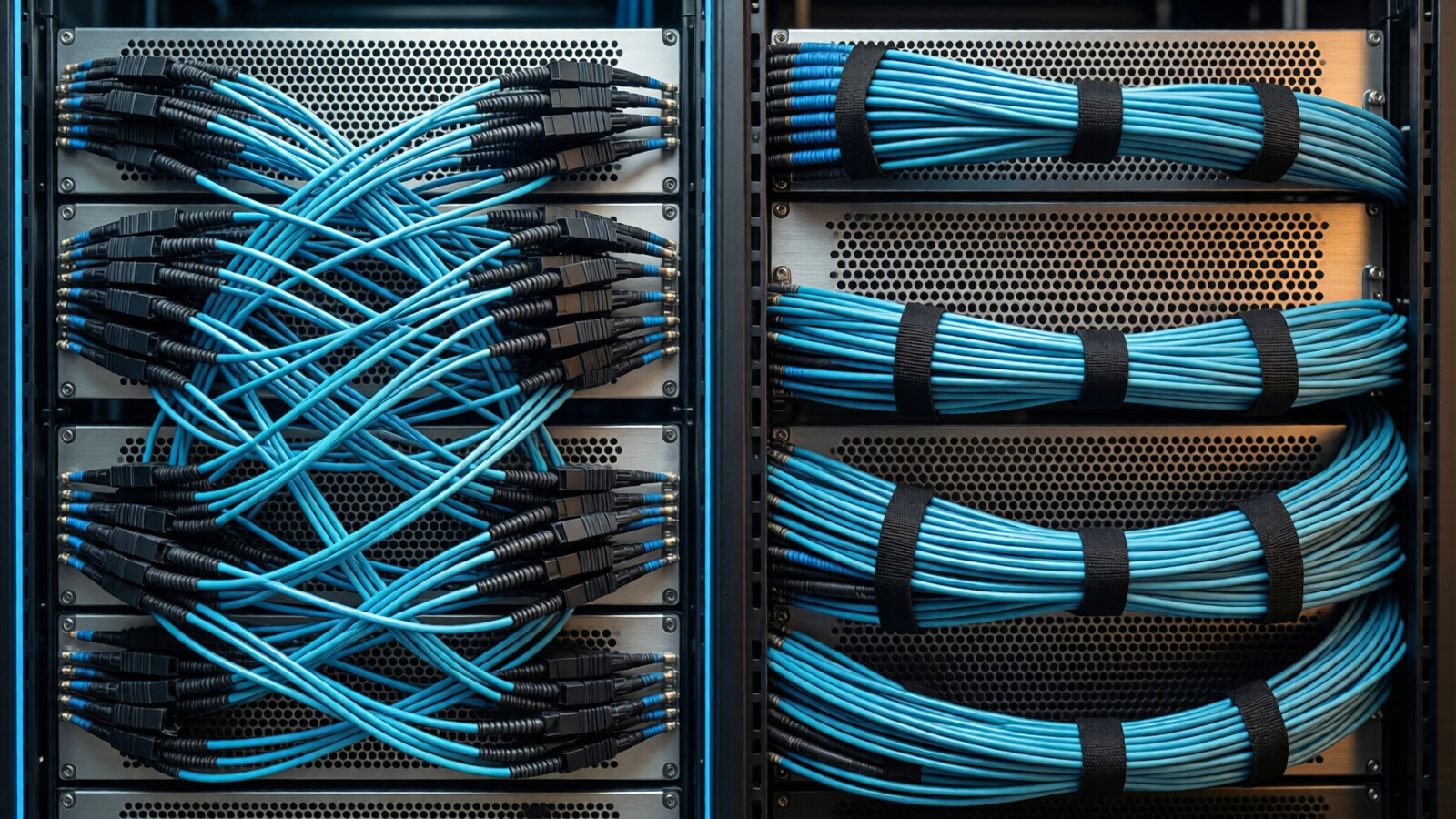
Slack management is where good intentions go wrong. The standard technician instinct is to coil surplus length neatly and tuck it into the side manager or behind the front door. Do that a hundred times in a row and you have built a dense annulus of jacketed cable with poor thermal conductivity, sitting in the exhaust path of the modules it serves. The coil does not just block intake air; it also traps warm air in the gap between the coil and the faceplate, encouraging recirculation at the exact boundary where the module’s intake should be seeing cold aisle air.
There is a second-order optical consequence that is rarely discussed. A coiled bundle carries residual tension into the connector. Over-tensioned cable pulls laterally on the module boot, and lateral load on a caged module can lift the module body slightly out of full seating. The module’s thermal path to the cage is through the top and bottom rails of the cage — it is a contact interface, not a solder joint. Partial unseating increases the contact thermal resistance, and the case temperature rises for reasons that have nothing to do with the module’s internal design. A module that measures 4 °C hot in one slot and normal in the next is often a mechanical problem, not an optical one.
Where the coil sits matters more than how tight it is
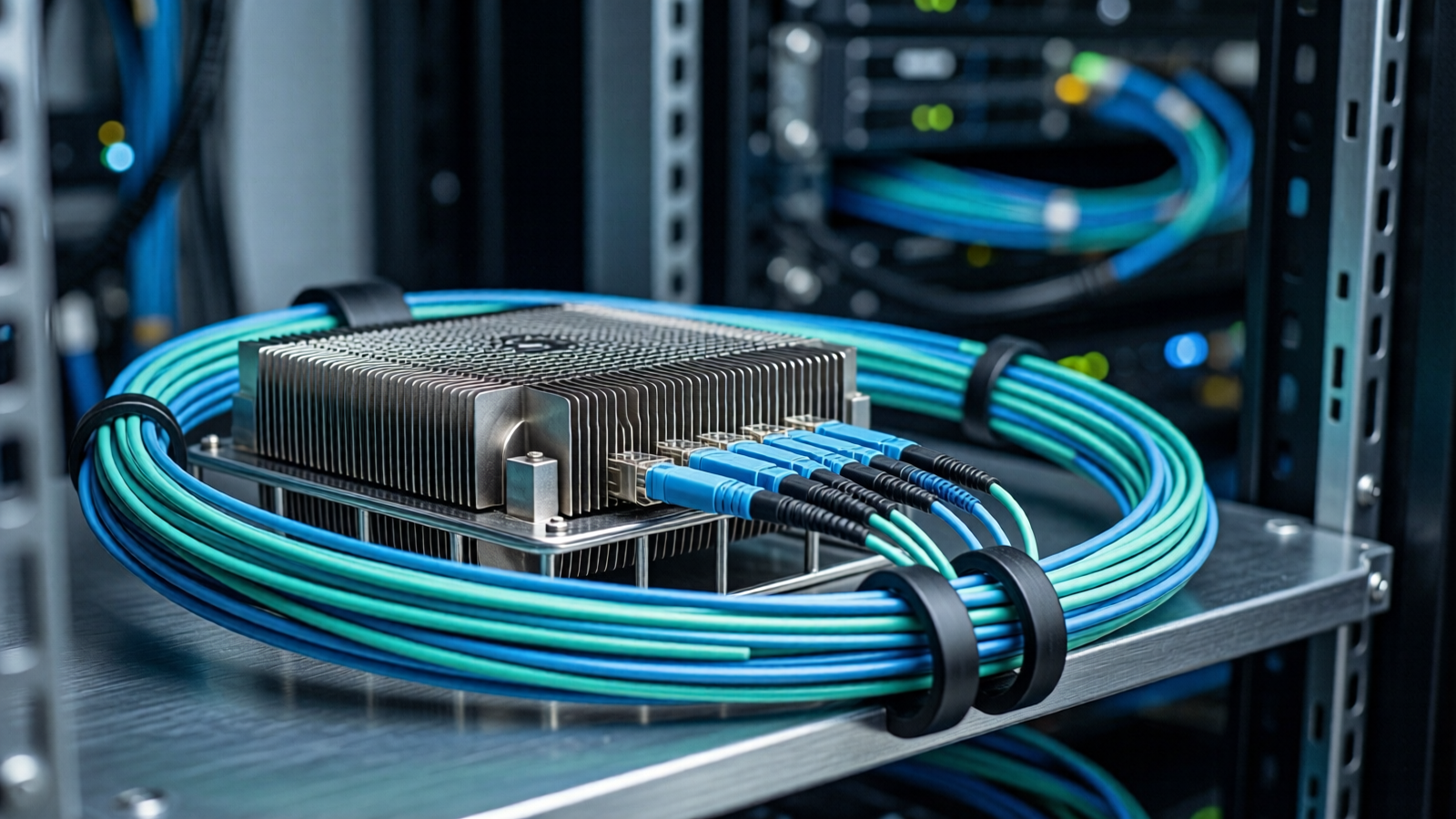
In a front-to-back chassis, the rear is the exhaust plenum. Fiber dressed along the rear of the rack, behind the switch, sits in air that has already absorbed the chassis heat load. Jacket materials are rated for it, but connector retention clips, strain-relief boots, and any labelling adhesive on that cable are living in the hottest air in the rack. Where a choice exists, dress slack to the side, at mid-depth, rather than along the rear top corner where exhaust concentrates.
| Routing practice | Optical consequence | Thermal consequence | Preferred alternative |
|---|---|---|---|
| Bundle dressed flat against faceplate | None directly | High — large intake area lost, whole-row flow drop | Layer to the side, stagger connector rows by depth |
| Slack coiled behind front door | Low risk if radius held | High — traps exhaust, drives recirculation | Side manager at mid-depth, loose figure-eight |
| Coil at or near minimum bend radius | Moderate — macrobend loss, margin erosion | Moderate — jacket contact, no air gap | Hold above minimum; use bend-insensitive cable where space truly is the constraint |
| Cable tension pulling on boot | Low | High — module unseats, contact resistance rises | Strain relief on the cable body, never on the connector |
| Slack dressed along rear top corner | Low | Moderate — adhesive and boots in exhaust air | Side routing at mid-depth, away from exhaust plume |
| Unused cages left open | None | High — bypass air starves adjacent modules | Port plug in every empty cage |
| Mixed cable lengths with excess looped per port | Low | High — unpredictable blockage geometry | Length-matched harnesses, pre-terminated trunks |
Case Temperature, Wavelength Drift, and Link Margin
Module case temperature is reported through the management interface and is exposed in the switch’s digital diagnostics. In most deployments it is monitored as a threshold alarm — warn at one value, shut down at another. Treating it that way wastes the most useful signal in the rack. Case temperature is a continuous proxy for how much optical margin you have left, and its effect on the link is gradual well before it is binary.
Three mechanisms connect the temperature reading to the error counters. First, laser wavelength drifts with temperature. A directly modulated or electro-absorption modulated laser without an integrated cooler drifts on the order of a tenth of a nanometre per degree Celsius, and CWDM grid channels are spaced 20 nm apart with a defined passband. A module running 15 °C above its design point has moved its center wavelength by roughly a nanometre and a half — small against the channel width, but not small relative to the margin budget on a link that is already tight. Second, extinction ratio and transmitter dispersion eye closure degrade as the device heats, which reduces the effective signal at the receiver. Third, receiver sensitivity itself drifts.
The consequence is that a heated link does not fail cleanly. It starts producing pre-FEC errors. With RS(544,514) KP4 forward error correction, the decoder can absorb a pre-FEC bit error ratio up to roughly 2.4×10⁻⁴. Below that threshold, everything looks perfect at the application layer while the FEC counters climb quietly. Above it, the link degrades quickly, and because FEC correction itself consumes latency and buffering, the first user-visible symptom is often a latency bump on a small fraction of flows rather than a link-down event. Teams that monitor only link state see nothing wrong until the day the ambient temperature rises four degrees.
There is also a lifetime argument. Laser wear-out follows an Arrhenius-type relationship, and the widely used planning rule of thumb is that every 10 °C of additional operating temperature roughly halves expected device life. A row of modules running at 70 °C instead of 60 °C because the faceplate is blocked has, in planning terms, half the service life. That cost lands years later and is almost never attributed to the cabling decision that caused it.
OSFP and QSFP-DD: heatsink geometry you cannot route around
The two dominant 800G form factors solve the thermal problem differently, and the difference changes the routing rules at the port.
OSFP is the physically larger package. Its extra height buys more heatsink fin area and more vertical separation from the neighbouring port, which is why it is the natural home for 800G and 1.6T optics at longer reaches and higher case-temperature classes. The same height is the routing problem: the cable exiting an OSFP port has less vertical clearance to the port above and below it, so the jumper must run straight for the length of the boot before any bend begins. Attempting an immediate upward or downward sweep to reach a side manager puts the bend right at the boot — simultaneously the worst place for bend radius and the best place to apply lateral load to the latch.
QSFP-DD keeps the familiar 1 RU density that made the QSFP family dominant, which means more ports per unit height and therefore less airflow available per port. The module is narrower and its heatsink is more compact, so it depends more heavily on uninterrupted faceplate airflow. In practice, a QSFP-DD row tolerates less cable intrusion than an OSFP row before temperatures move, and it has a shorter boot, so bend geometry must be resolved within a smaller envelope.
The routing consequence for both: breakout as far from the faceplate as the link budget permits. Terminating a trunk in a high-density panel and using short, length-controlled breakouts at the switch keeps the long cable mass and the bulk of the slack away from the intake face. The structural argument for that architecture is set out in our MPO/MTP fiber solutions selection framework, and it happens to be the single highest-leverage thermal decision available to a cabling designer.
Air-Cooled and Liquid-Cooled Boundaries: Where Routing Rules Change
The assumption most teams carry into a liquid-cooled project is that liquid cooling solves the thermal problem. For the switch ASIC, it largely does. For the optics, it frequently makes things worse.
Direct-to-chip liquid cooling puts a cold plate on the processor and removes the majority of the chassis heat load, which allows fan speeds to drop substantially — or, in some designs, allows fans to be reduced to a small number of low-speed units dedicated to auxiliary components. The optics did not move. They are still on the faceplate, they still dissipate 14–32 W each, and they are still air-cooled. The airflow that used to be delivered by fans sized to cool a 500 W ASIC is now delivered by fans sized to cool a much smaller residual load. Faceplate velocity falls, and the cable blockage that was tolerable in an air-cooled chassis becomes the dominant term.
This creates the characteristic hybrid-rack failure: the ASIC runs cool, the coolant loop looks healthy, and the optics run hotter than they did in the previous fully air-cooled generation. The design lesson is that faceplate airflow in a liquid-cooled rack must be specified as a requirement in its own right — a minimum velocity or a minimum volumetric flow across the optical ports — and not inherited implicitly from the ASIC cooling solution. Where the chassis supports it, dedicating fans to the optics zone and documenting the resulting faceplate airflow is the difference between a working liquid deployment and a rack that periodically drops links.
| Cooling architecture | Where the heat goes | Cabling implication | What to specify explicitly |
|---|---|---|---|
| Conventional front-to-back air | All chassis heat to room air | Faceplate blockage is the primary variable; keep intake clear | Faceplate velocity at planned port population, plus derating for cable mass |
| Air with rear-door heat exchanger | Most heat captured at rear coil | Rear space is occupied by the coil; route fiber to the side | Rear clearance and side routing path, coolant line separation from fiber |
| Hybrid direct-to-chip liquid plus fans | ASIC to coolant, optics and auxiliaries to air | Reduced fan speed raises the value of every clear intake area | Minimum faceplate airflow dedicated to optics, independent of ASIC load |
| Full immersion | Everything to dielectric fluid | Standard patch cords and connectors are not qualified for direct immersion | Fluid compatibility of jackets, adhesives and connector housings; service procedure |
Immersion deserves a separate caution rather than a routing tip. Immersion cooling is thermally attractive for high-density compute, but the optical layer is the part of the system least prepared for it. Jacket compounds, strength members, strain-relief boots, and the adhesives used in connector assembly are generally qualified for air, not for prolonged contact with dielectric fluid, and the same applies to the indexing gel and polish geometry at the ferrule interface. Any immersion design that includes optical interconnect needs fluid-compatibility confirmation from the cable and connector supplier, plus a service procedure that accounts for fluid loss and contamination during mate and demate. Absent that, the safe architectural answer is to keep the optical breakout outside the tank.
The boundary at which a project should move from air to liquid is therefore not simply a wattage threshold. It is the point at which the optics load per rack unit approaches the airflow the chassis can deliver at the ambient you can actually guarantee — which in most facilities is several degrees above the design ambient on the hottest afternoons. If a fully populated 800G row is running within a few degrees of its case-temperature limit at nominal ambient, there is no thermal headroom left for a cabling change, a filter loading cycle, or a fan failure. That is the signal to change architecture, not the moment the temperature alarm fires.
Thermal-Aware Fiber Routing: A Pre-Deployment Checklist
The items below are ordered by when they should be decided, not by importance. The first four are design decisions that are almost free before procurement and extremely expensive after installation.
- ☐ Count the optics heat load per rack unit at planned port population, using datasheet maximum power, and compare it to the chassis thermal specification at the ambient you can guarantee — not the ambient in the design document.
- ☐ Choose the breakout location deliberately. Terminate trunks in a high-density panel and keep breakouts short at the switch, so long cable mass and slack never sit in front of the intake face.
- ☐ Reserve a side routing path of adequate cross-section in the rack elevation, and document it, so installers have a defined destination for slack that is not the front door.
- ☐ Specify port plugs and rack blanks as line items, not as an afterthought, and make “every empty cage plugged” an acceptance criterion.
- ☐ Length-match harnesses per port group. Excess looped per port is the single largest source of unpredictable blockage geometry.
- ☐ Verify installed bend radius on a sample of the run, after dressing, with the door closed — the door is what turns an acceptable route into a pinched one.
- ☐ Train strain relief at the cable body, not at the connector boot. Confirm no lateral load on module latches.
- ☐ Check module seating on every port after dressing; a partially seated cage is a hot module regardless of airflow.
- ☐ Record a baseline: per-port case temperature and pre-FEC error counters at commissioning, at known ambient.
- ☐ Set monitoring on the row mean and the spread, not only on absolute thresholds; a rising mean after a cabling change is the earliest available warning.
- ☐ Re-baseline after every cabling change, and treat any step change in the spread between ports as a mechanical or blockage finding.
- ☐ In liquid-cooled racks, specify faceplate airflow to the optics zone explicitly and verify it with the ASIC at idle, when fan speed is at its lowest.
- ☐ Audit blanking panels and door closure as a periodic task; both degrade silently after the initial installation.
- ☐ Document the routing standard with drawings, so the next technician reproduces the geometry instead of improvising it.
None of these items requires new hardware. Most of them are decisions about placement and discipline, and the reason they get skipped is organizational: the cabling plan is owned by one team, the thermal budget by another, and the acceptance test by a third. Where a single engineer owns the port-level layout end to end, the problems described in this article mostly do not occur. Where ownership is split, the cables end up exactly where the shortest path puts them, and the thermal consequences are discovered months later in a link-flap investigation.
For the optical layer, the enabling components are already mature — high-density MPO and MMC patch cords, panels and cassettes, and cross-connect architectures that move the shuffle out of the switch row entirely. The Infinity shuffle OXC approach to AI data center interconnect is one example of how relocating the physical cross-connect changes both the fiber mass at the faceplate and the serviceability of the row. The thermal benefit is a by-product of the architecture, but it is a real one and worth counting when the business case is built.
Frequently Asked Questions
How much airflow does a dense MPO bundle actually block?
There is no single number, because it depends on bundle shape, cable diameter, and how tightly the cables are dressed against the perforations. What matters is that blockage is measured as lost open area at the intake plane, and that the resulting pressure-drop penalty applies to the whole chassis, not just the blocked ports. A row with two-thirds of its intake face covered by dressed cable will show elevated case temperatures across all ports, including ports far from the bundle. Measure rather than estimate: record per-port case temperature before and after dressing and treat any uniform upward shift as an airflow finding.
Does using smaller MMC or VSFF cable reduce front-panel congestion?
Per cable, yes — a smaller connector and jacket reduce the bend envelope and the frontal area of that individual cable. At the rack level the answer is usually no, because fiber count per port grows at the same time. Going from one MPO-12 per 400G link to two MPO-12 or MPO-16 per 800G link roughly doubles connector count, which offsets most of the per-cable area reduction. The reliable way to reduce front-panel congestion is architectural: move the breakout away from the faceplate rather than shrinking the cable at it.
At what case temperature should I be worried about link margin?
Use the module datasheet’s operating case temperature range as the hard limit and treat anything within roughly ten degrees of that limit as a margin problem rather than a margin success. The useful early indicator is not the absolute value but the trend: rising pre-FEC error counters alongside rising case temperature on the same ports. Because KP4 FEC can absorb a pre-FEC bit error ratio up to about 2.4×10⁻⁴, a link can look completely clean at the application layer while its margin is being consumed.
Does liquid cooling the switch ASIC make the optics run cooler?
Usually not, and it can make them run hotter. Direct-to-chip cooling removes ASIC heat and allows fan speeds to fall, but the optics stay on the faceplate and stay air-cooled. Lower fan speed means lower faceplate velocity, so the same cable blockage that was acceptable in an air-cooled chassis becomes the limiting factor. Faceplate airflow for the optical zone should be specified as its own requirement in liquid-cooled racks, not inherited from the ASIC cooling design.
Is it better to coil slack in the side manager or behind the front door?
Side manager, at mid-depth, every time. Slack coiled behind the front door sits directly in front of the intake face and traps exhaust air in the gap between the coil and the faceplate, which encourages recirculation. Side routing at mid-depth keeps the intake plane clear and keeps the cable out of the hottest exhaust region at the rear of the rack. Hold the installed bend radius well above the manufacturer minimum while doing it.
How does a cabling problem make a module run hot without any airflow change?
Through mechanical load. A module’s thermal path runs through the contact between its body and the cage rails, so a module that is not fully seated has a higher contact thermal resistance and runs hotter at identical airflow. Cable tension pulling laterally on a boot, or a bundle resting on a connector, can lift a module slightly out of its cage. That is why a single hot slot surrounded by normal ones is worth investigating as a mechanical finding before replacing the optic.
High-density optical interconnect is a systems problem, and the thermal and physical layers of it are now inseparable. Teams that plan the two together — heat load per rack unit, breakout location, side routing path, plugged cages, measured baseline — get racks that stay inside their thermal design envelope through a full population cycle. Teams that plan them separately get a rack that passes acceptance on day one and starts dropping margin as soon as it is fully built out. For a broader view of how optical interconnect decisions cascade into AI cluster architecture, see our analysis of how optical interconnect is reshaping data centers, and for the thermal-wall context at the cassette level, the earlier piece on breaking the 51.2T thermal wall covers the product-side solution space. Co-packaged and near-packaged architectures shift some of this burden off the faceplate, but they introduce their own deployment constraints, as examined in our notes on CPO optical interconnect and deployment challenges and the companion analysis of optical interconnect adoption and deployment reality; the emerging trend picture is summarized in our review of co-packaged optics evolution. Standards work on the electrical and optical interfaces themselves is published by the IEEE 802.3 Ethernet Working Group and OIF, while rack-level thermal and density practice is addressed through Open Compute Project contributions and the TIA infrastructure standards.