


Optical connectivity in an AI data center is not a purchasing decision. It is a specification decision, and the two are separated by about eighteen months. Buying the wrong transceiver costs you a swap; specifying the wrong connector format, polarity convention or loss budget costs you a re-cabling window, a maintenance outage and a rack full of hardware that cannot reach its rated port count. By the time the fabric is live, most of the physical layer is no longer changeable without a shutdown.
This guide is written for the point where an AI cluster is still on paper. It covers the decisions that have to be locked before the purchase order goes out: connector format, fiber count and lane mapping, polarity, loss budget, endface quality, physical density, termination strategy and migration headroom. Each section states what to specify rather than what to buy, because the specification is what survives a vendor change.
Why optical connectivity became a specification problem
In a 10G or 25G data center, the physical layer was forgiving. A two-fiber duplex link had one polarity to get right, one connector type to standardise, and enough loss margin that a dirty endface would usually still pass traffic. Installed base inertia did most of the specification work: if everything was LC duplex, nothing needed deciding.
Four changes broke that arrangement at the same time. Lane counts rose from one or four to eight and sixteen, which turned a single link into a parallel channel where every lane has to arrive in the right position. Connector formats multiplied as density pressure pushed the industry from LC duplex toward multi-fiber push-on and then to very small form factor bodies. Reach and loss tolerances tightened as linear and co-packaged designs removed the digital signal processing that used to absorb a marginal channel. And port counts per rack grew fast enough that cable management stopped being housekeeping and became a thermal and serviceability constraint.
The net effect is that two teams can buy components that are individually compliant and build a link that does not work. The parts are not the problem; the interfaces between them are. That is exactly what a specification is supposed to close.
The layer model: what you are actually specifying
It helps to separate the physical layer into five specification layers, because they are owned by different people and change on different cycles. Treating them as one bundle is where most projects lose control.
- Optical interface. The module’s lane count, signaling rate, reach class and connector receptacle. This is set by the switch and optics vendor and is largely non-negotiable.
- Connector and ferrule. MPO or MTP bodies in 8, 12, 16 or 24 fiber counts, or VSFF formats such as MMC, with a defined polish and endface geometry.
- Cable and assembly. Trunk, harness or patch cord, with a stated fiber type, jacket rating and per-lane loss allowance.
- Distribution and management. Patch panels, cassettes, ODF frames and shuffle hardware that convert many trunk ends into an operable front panel.
- Physical environment. Rack unit allocation, bend radius, airflow path, labeling scheme and service access.
Layers one and two determine whether the link is possible. Layers three to five determine whether it is operable at scale. Projects that specify only the first two end up with a working prototype and an unmaintainable production fabric.
Connector format: MPO, MTP and when VSFF becomes mandatory
MPO and MTP are both multi-fiber push-on connectors built on an MT-style ferrule; MTP is a licensed refinement of the MPO design rather than a different interface concept. In practice they mate with each other when the fiber count, gender and polish match. The distinction that matters for a specification is not the brand name but the four attributes that have to be called out explicitly: fiber count, gender, polish and key orientation.
The fiber count decision follows the lane count. Twelve-fiber bodies suit eight-lane 400G links with four fibers unused, sixteen-fiber bodies suit eight-lane links with no waste, and twenty-four-fiber bodies are common where a trunk has to carry several links of lower lane count. Whichever you choose, the choice has to be consistent across every cassette, panel and adapter in the channel, because a 12-fiber trunk that lands on a 24-fiber panel port is a mapping error that only appears at commissioning.
VSFF formats enter the specification when front-panel density reaches the point where MPO bodies consume too much rack face. An MMC connector carries the same fiber count in roughly one third of the footprint, which is what makes 800G and 1.6T port counts physically realisable in a standard rack. The trade-off is that VSFF bodies demand tighter bend control and more disciplined labeling, and mixing VSFF and MPO on the same panel without a documented mapping is a reliable way to create polarity faults. The connector-level differences and the migration path between formats are covered in the MMC vs MPO VSFF migration guide.
What to write into the specification: fiber count, gender (pinless or pinned), polish (APC or UPC, and consistently across the channel), key orientation, and the ferrule endface geometry standard you will accept. Leave a vendor to infer any of these and you will receive a mix.
Fiber count and lane mapping: sizing for 400G, 800G and 1.6T
Fiber count is usually specified from the module, which is the wrong direction. The number that has to be defensible is the count per rack, not per link, because that is what the trunk, the panel and the pathway have to accommodate.
Work it in three steps. First, convert ports into lanes: a 400G port at eight lanes needs eight fibers, an 800G port at eight lanes needs eight fibers at twice the rate, and a 1.6T port needs sixteen lanes at current signaling rates. Second, add the growth factor you are actually funded to install rather than the one you hope for. Third, express the result as trunk assemblies of a standard count, and check that the panel positions divide evenly into those counts.
Lane mapping is where fiber count becomes operational. A trunk that carries four 400G links over 32 fibers is only usable if the panel breaks those fibers out into the same four groups at both ends, in the same order. If the mapping is not documented and labeled at both ends, every future repair becomes a discovery exercise. Specify the mapping as a table, not a sentence, and require the cable assembly vendor to supply it with the delivery.
Polarity: the failure that passes every test
Polarity errors are the most expensive class of physical layer fault because they do not show up in a loss test. A link with inverted lane order measures within budget on every fiber and still fails to carry traffic, which sends the commissioning team looking at optics, firmware and configuration before anyone thinks to check the connector.
Three methods are in general use, and each produces a different lane ordering. The method only works if it is applied consistently from the switch port to the network interface port, through every cassette, adapter and panel in the channel. Mixing methods mid-channel is not a degraded link; it is a link that will not come up. The conventions and their lane level consequences are set out in the fiber polarity methods A, B and C guide.
Two specification rules prevent almost all of this. State the polarity method for the channel, and require every assembly and cassette in that channel to be delivered pre-configured to it, with a visible label at both ends. Then require polarity verification as a commissioning step with recorded results, rather than assuming it from the bill of materials. On a 384-port fabric, the difference between verifying polarity during installation and discovering it afterwards is a maintenance window.
Loss budget: the four terms that decide whether the link works
A loss budget is a subtraction, and the result has to stay positive after every term is counted honestly. Four terms dominate: connector loss, splice loss, fiber attenuation and margin.
Connector loss is not a single number. A mated pair has a loss that depends on endface quality, alignment and polish, and the specification should state both the per-pair allowance and the number of mated pairs in the channel rather than an average per connector. Splice loss matters in any build that is not fully pre-terminated. Fiber attenuation is a per-kilometer figure that depends on wavelength and fiber type, so it has to be calculated at the operating wavelength rather than taken from a general table. Margin is the term that projects routinely under-specify, and it is the one that absorbs every unknown in the field: temperature, aging, re-mating, and the ordinary degradation that no installation is immune to.
The calculation method, typical values and a worked example are set out in the optical loss budget calculation guide. Two habits are worth carrying into the specification: compute the budget per lane rather than per link, because the worst lane governs; and record the measured value at commissioning so that a later drift can be judged against a baseline instead of a recollection.
Endface quality: the cheapest yield gain available
Contamination is the most common single cause of excess loss in a new build, and it is entirely preventable. Every connector that enters a port carries whatever it picked up in packaging, on a patch panel, or on a technician’s hands. A single particle on a single fiber in a sixteen-lane channel is enough to fail the link.
Inspection is the part that gets skipped under schedule pressure, which is why it belongs in the specification as a hold point rather than a good practice. Require inspection of every endface before mating, using a scope with the acceptance criteria defined by IEC 61300-3-35 rather than a visual check. Require a defined cleaning procedure: dry cleaning as the default, wet cleaning for contaminated endfaces, and inspection after cleaning rather than before. And require rejected connectors to be recleaned and reinspected rather than wiped and used.
The procedures and acceptance zones are covered in the endface cleaning and inspection guide, and the handling rules that prevent mechanical damage during patching are in the MPO/MTP jumper installation tips. On a large fabric this is the highest return item in the entire physical layer, because it costs technician hours rather than hardware.
Cable management and physical density: the constraint nobody specs
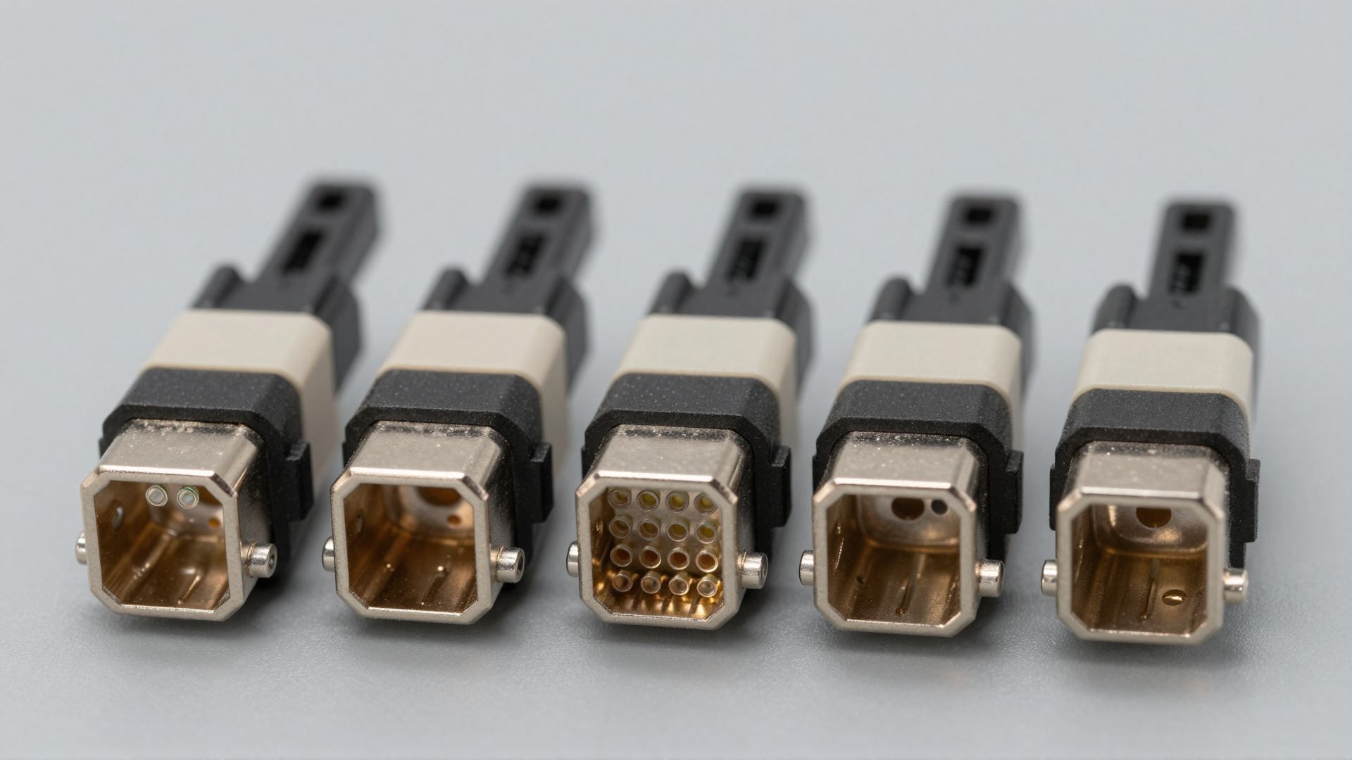
At high port counts, the rack face becomes the scarce resource and cable volume becomes a thermal variable. A trunk assembly that bends below its minimum radius loses more than it should and, in the case of ribbon fiber, can fail outright a month after installation. A patch field that fills the airflow path raises intake temperature, which reduces optics reliability across the whole rack.
Four physical constraints belong in the specification because they are cheap to state and expensive to retrofit. Bend radius: state the minimum for installed and for during-installation conditions, and require assemblies rated for both. Pathway: state the vertical and horizontal cable management capacity in fiber count, not in units, and check that the count you calculated earlier fits. Service access: state that any single connector must be reachable and replaceable without disturbing more than its neighbours, which in practice rules out certain high-density front-panel configurations. Airflow: state whether the patch field is in the cold aisle, the hot aisle or a contained volume, and specify the panel design accordingly.
Labeling is the fourth constraint and it is usually treated as an afterthought. A fabric with 8,000 fibers and no consistent labeling scheme is not maintainable, because every fault becomes a physical trace. Specify the scheme, specify that labels are applied at both ends, and specify that the mapping table is delivered as a document that matches the labels.
Pre-terminated or field-terminated: the decision that sets your schedule

Pre-terminated assemblies arrive with factory-polished, factory-tested endfaces and a measured loss per fiber. Field termination trades that for schedule flexibility and lower logistics cost. The choice affects the loss budget, the commissioning plan and the skill level required on site, which makes it a specification item rather than a procurement preference.
The usual resolution is a hybrid: pre-terminated trunks for the long runs between rows and into the rack, field termination only where a run has to be cut to length after installation, and factory-terminated patch cords throughout the front panel. Whatever the split, the specification should require measured per-fiber loss data with the delivery, because that data is what makes the commissioning test a verification step instead of a discovery step. The trade-off analysis, including where each approach wins on cost and schedule, is covered in the pre-terminated vs field-terminated cabling comparison.
Migration headroom: specifying so you do not re-cable
An AI fabric that is specified for its first generation of optics will be re-cabled before it is depreciated. The question is whether that re-cabling is a panel change or a pathway change, and that is decided at specification time.
Three forms of headroom are worth buying. Fiber count headroom in the pathway, so that a future trunk can be added without new containment. Connector format headroom at the panel, achieved by choosing a modular panel where the cassette or module defines the connector and the chassis does not. And port count headroom in the rack, achieved by choosing a distribution platform whose density ceiling is above the current requirement.
The economics are straightforward: modular distribution hardware costs a fraction of a construction project, and the difference between a modular and a fixed panel is small at purchase. The relevant platforms include the GPX80 modular fiber distribution panel, the GPX77 vertical modular ODF and the GPX78 inline shuffle panel. Where the fabric moves to optical switching, the panel design has to accommodate shuffle and cross-connect patterns rather than simple port breakout, which is a different requirement set and is treated separately in the Infinity Shuffle OXC platform and the optical backplane for AI infrastructure.
What to put in the specification document
The table below is the minimum set. Each row is a decision that, if left open, will be made by a vendor or by the installation crew, and either way it will not be documented.
| Item | What to state | Why it matters |
|---|---|---|
| Connector format | MPO/MTP or VSFF, fiber count, gender, polish, key orientation | Determines mate compatibility across every assembly in the channel |
| Lane mapping | A table of port to fiber positions at both ends | Makes breakouts repeatable and repairs traceable |
| Polarity | Method A, B or C, applied end to end, with verification records | Prevents the fault that passes loss testing and fails traffic |
| Loss budget | Per-lane budget with connector, splice, fiber and margin terms itemised | Defines the acceptance threshold at commissioning |
| Endface | IEC 61300-3-35 acceptance zones, inspection and cleaning procedure | Removes the most common cause of excess loss |
| Fiber type | OM4 or OM5 multimode, or single-mode grade, per run | Sets attenuation and reach assumptions in the budget |
| Termination | Pre-terminated, field-terminated or hybrid, with per-fiber loss data | Sets schedule, skill requirement and verification method |
| Density and access | Rack units, panel type, front or rear access, service clearance | Determines whether the fabric stays operable at scale |
| Physical constraints | Bend radius, pathway capacity in fibers, airflow zone, labeling scheme | Prevents thermal and mechanical failures after handover |
| Acceptance | Test method, instrument type, sampling or full-fiber coverage, record format | Turns commissioning into verification rather than discovery |
Acceptance testing: what to measure and what to keep
A commissioning test has one purpose: to prove that the installed channel matches the specified budget. That requires three things to be defined in advance. The method, which for multi-fiber links means a per-fiber measurement rather than a single link figure. The coverage, which for a first build should be every fiber rather than a sample, because the defects that matter are individual endfaces. And the record, which should be a per-fiber value stored against the fiber identifier, so that a future fault can be compared against the day-one number.
Two further checks belong in acceptance and are routinely omitted. Polarity verification, recorded per link rather than inferred from the bill of materials. And endface inspection of any connector that was opened during installation, including those that were re-mated after a test. Both are cheap at handover and expensive afterwards.
Where the standards sit
Most of the values in a specification trace back to a small number of published documents, and citing them is what makes a requirement enforceable rather than advisory. Structured cabling and data center topology expectations are published by TIA. Fiber optic connector inspection and endface acceptance criteria are defined in IEC standards. Ethernet lane rates and reach objectives, which drive most lane-count decisions, come from the IEEE 802.3 working group. Electrical and optical interface agreements for high-speed signaling are published by the OIF, and single-mode fiber characteristics by the ITU-T. A specification that references the applicable standard for each requirement survives a change of supplier; one that references a supplier’s datasheet does not.
Putting it together
The specification sequence that works is: fix the optical interface from the switch and optics decision, derive lane count and fiber count per rack with a stated growth factor, choose the connector format that makes that count physically realisable, lock one polarity method for the whole channel, compute a per-lane loss budget with an honest margin, then specify endface, termination, density and acceptance against published standards. Every one of those steps produces a document, and the documents are what the installation is judged against.
The related design decisions sit in the component guides: trunk sizing, lane mapping and installation rules in the MPO/MTP trunk cable guide; the full selection framework for an AI fabric in the MTP/MPO solutions design guide for 400G and 800G; connector differences at the patch cord level in the MPO vs MTP patch cord comparison; and the link-level implications of removing DSP from the module in the LPO deployment guide. Product-level options across the whole chain are collected in the AI data center optical connectivity solutions range, including the high-density MMC fiber cassette and the MPO-ELSFP connector patch cord.
Frequently asked questions
Should a new AI fabric specify MPO or VSFF connectors?
It depends on the port count you need to fit on the rack face, not on the optics generation. Below the density where MPO bodies fit comfortably, MPO keeps the supply chain simple and the field tooling familiar. Above it, VSFF is what makes the port count physically realisable. The constraint to check first is bend radius and labeling discipline, because VSFF forgives neither.
How much fiber count headroom should be installed on day one?
Enough that the next generation of optics can be connected without new containment. Practically, that means sizing the pathway for the port count you are funded to reach and installing trunks to the count that keeps panel positions aligned, rather than filling every position on day one. Fiber is cheap relative to construction; pathway capacity is the item that is expensive to add later.
Can a channel mix polarity methods if the loss budget still passes?
No. Polarity is a lane ordering property, not a loss property, so a mixed channel measures within budget and still fails to pass traffic. One method has to apply across every cassette, adapter, panel and cord in the channel, and it has to be verified at commissioning rather than assumed from the ordering documents.
Is a per-link loss measurement sufficient for acceptance?
Not for a parallel multi-fiber link. A per-link figure averages across lanes and hides the single contaminated or damaged fiber that will fail the channel in service. Acceptance should record a per-fiber value against the fiber identifier, which also gives you the baseline for judging later drift.
When does endface inspection stop being optional?
It never was optional; it is only sometimes skipped. Every connector that enters a port should be inspected against the acceptance criteria before mating and after any re-mating during installation. On a high-lane-count fabric this single procedure removes the largest category of excess loss at the lowest cost.
How should the physical layer be specified for a future optical switching upgrade?
By choosing distribution hardware whose chassis is independent of the connector format and whose pattern supports cross-connect and shuffle layouts rather than only port breakout. That is a panel-level requirement, and it is much cheaper to satisfy at initial purchase than to retrofit around a fixed panel design.
Bottom line: the parts in an AI data center physical layer are commodity items; the interfaces between them are not. Specify connector format, lane mapping, polarity, loss budget, endface acceptance, density and termination as documents with standards behind them, verify polarity and per-fiber loss at commissioning, and keep the records. Everything that goes wrong in a live fabric traces back to one of those items having been left to inference.