


Rack space stopped being free somewhere around the 400G transition. A single 1RU switch now terminates 32 to 64 high-speed ports, and every one of those ports needs a duplex optical path that runs back to a patch panel, a trunk cable, and eventually a spine. For a decade the LC duplex connector absorbed that growth, because it was small, reliable, and available from every vendor on earth. It still is. The problem is arithmetic: LC occupies a 6.25 mm port pitch, and once a rack fills with 400G and 800G optics, the front panel runs out of millimetres long before it runs out of switch capacity.
The CS connector is one answer to that arithmetic problem. It puts two 1.25 mm ferrules side by side in a single push-pull housing, keeps the same physical-contact polish and the same single-mode and multimode performance envelope as LC, but halves the width per duplex pair. In practical terms, that is the difference between a 1RU panel holding 48 duplex ports and the same panel holding 96. This guide walks through what CS is, where it earns its place, how to design a link around it, and which mistakes reliably cost teams a maintenance window.
If you are still deciding whether to standardize on CS at all, the more useful comparison may be the wider family of small-form-factor and multi-fiber options — our breakdown of the MMC vs MPO vs very-small-form-factor connector migration path covers the strategic view, and the MPO/MTP selection framework for AI data centers covers the trunk side. This article stays focused on the duplex edge.
What a CS Connector Actually Is
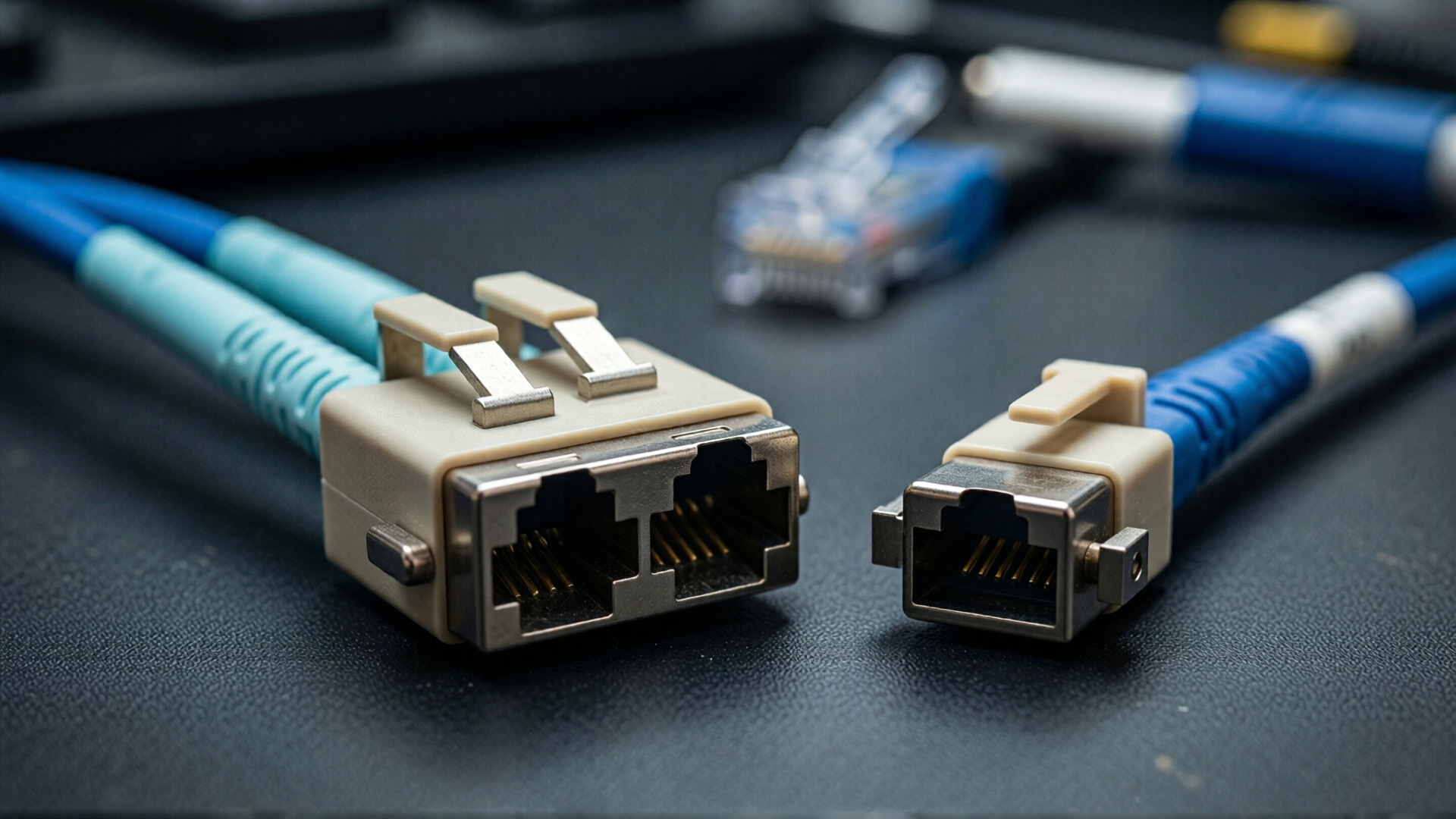
CS is a duplex optical connector built around two independent 1.25 mm ceramic ferrules. Each ferrule carries one fiber, so one CS connector terminates two fibers — transmit and receive in a standard duplex link. The housing latches with a push-pull boot, and the two ferrules are spring-loaded individually, which means each fiber keeps its own physical contact force rather than sharing one through a common block.
Three properties follow from that design, and they explain most of the engineering trade-offs downstream.
- Ferrule compatibility. Because the ferrule is the same 1.25 mm zirconia part used in LC, the polish geometry, the endface inspection criteria, and the cleaning workflow carry over unchanged. Technicians are not learning a new optical interface — they are learning a new latch.
- Halved footprint. Two fibers fit into a body roughly the width of one LC duplex position. This is the entire commercial case for CS: density per rack unit and per panel opening.
- Duplex-native topology. Unlike MPO, CS maps one connector to one duplex link. There is no 8-fiber or 12-fiber breakout to reason about at the panel, which keeps polarity and documentation models close to what LC-trained teams already run.
The connector interface itself is standardized within the IEC 61754 series of fiber optic connector interface documents, published and searchable through the IEC Webstore connector interface catalogue. Where a project requires formal compliance evidence, cite the specific part number rather than the family name.
CS vs LC vs SN vs MDC vs MPO: The Density Math
Density claims are easy to make and hard to compare, because vendors measure ports, fibers, and rack units differently. The only honest way to evaluate CS is to hold the enclosure constant and count what actually fits in a 1RU panel with usable cable management behind it.
| Connector | Fibers per connector | Ferrule | Typical port pitch | Duplex ports per 1RU (typical) | Best fit |
|---|---|---|---|---|---|
| LC duplex | 2 | 1.25 mm | ~6.25 mm | 24 to 48 (48 to 96 fibers) | General purpose, mixed-vendor environments |
| CS duplex | 2 | 1.25 mm | ~3.8 mm | 48 to 72 (96 to 144 fibers) | 400G/800G duplex edge, high port count |
| SN (2 x duplex) | 4 | 1.25 mm | ~3.8 mm | 24 to 36 connectors (96 to 144 fibers) | Quad-style 400G/800G optics |
| MDC duplex | 2 | 1.25 mm | ~3.8 mm | 48 to 72 (96 to 144 fibers) | Density where push-pull boot access is critical |
| MPO-8 / MPO-12 | 8 / 12 | MT ferrule | n/a (single body) | Up to 576 fibers in highest-density frames | Trunks, spine links, parallel optics |
| MPO-16 / MPO-32 | 16 / 32 | MT ferrule | n/a (single body) | Up to 1,152 fibers in highest-density frames | 800G and 1.6T parallel links |
Read the table as an order-of-magnitude tool, not a datasheet. Real numbers depend on adapter panel design, boot clearance, whether the panel is angled, and how much vertical space the rear cable manager consumes. What the table does establish is the shape of the problem: moving from LC to CS roughly doubles the duplex paths a fixed-width panel can terminate, while MPO moves the argument onto a completely different axis — one connector, many fibers, and a breakout or trunk architecture behind it.
Why the 1.25 mm Ferrule Matters More Than the Housing
It is tempting to treat CS as a mechanical curiosity. It is not. The optical performance of a CS link is inherited almost entirely from the ferrule and the endface geometry, both of which come straight from the LC ecosystem. Insertion loss for a good single-mode CS pair sits in the same range as a good LC pair; return loss is governed by the same APC or UPC polish choice; and multimode bandwidth behavior is a property of the fiber, not the latch.
What changes is tolerance stacking. Two ferrules in one housing means two independent spring forces, two endface geometries, and two opportunities for a partially seated connector. A CS connector that is 90 percent latched can look seated while one of its two fibers is air-gapped. That single failure mode is responsible for more CS-related trouble tickets than any optical shortcoming of the design, and it is why insertion loss should always be validated per fiber, not per connector pair.
Where CS Fits in 400G and 800G Architectures
The optics roadmap is what pushed duplex density to the front of the queue. 400G and 800G client optics are commonly built as 8 x 50G or 8 x 100G lanes, and those lanes reach the front panel either as parallel MPO interfaces or as breakout duplex interfaces. When the design uses MPO at the switch and duplex at the server, the panel becomes a translation layer: MPO trunks land on the rear, duplex ports present on the front, and the number of front ports determines how many servers a single rack unit of patching can serve.
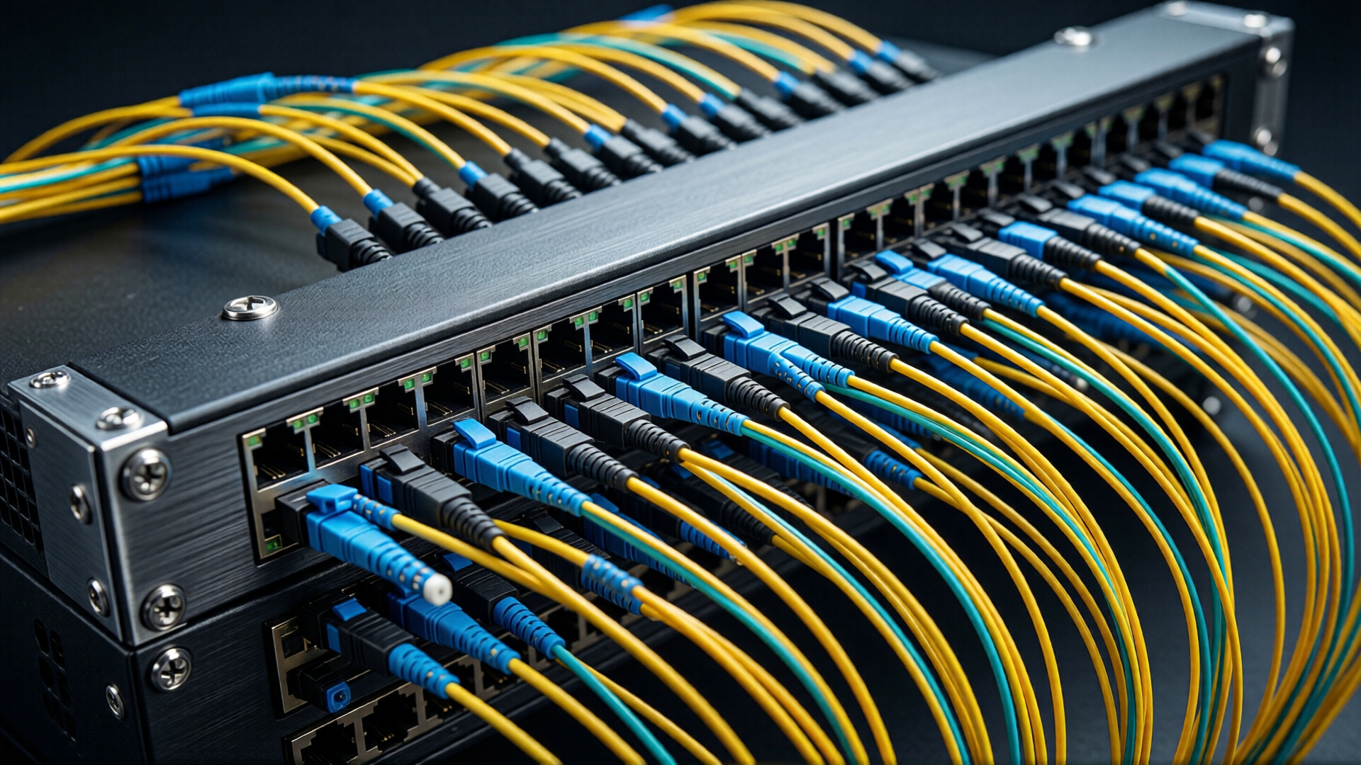
That is precisely the seam where CS pays for itself. A rack serving 400G leaf switches with duplex fan-out needs two fibers per server port. At LC density, a 1RU panel realistically supports 48 duplex ports. At CS density, the same 1RU supports up to 72 in typical implementations, and 96 in the highest-density frames. Over a 42RU rack, that compounds into a meaningful reduction in patching rows — and in the number of panels, panels’ worth of adapters, and cubic metres of jumper that must be ordered, labelled, and maintained.
The MPO Trunk to CS Breakout Pattern
The most common CS deployment pattern looks like this: an MPO-16 or MPO-24 trunk leaves the spine, terminates on the rear of a high-density panel, and is broken out to duplex CS ports on the front. Individual CS patch cords then carry a single duplex link to each server NIC. The topology is functionally identical to the MPO-to-LC breakout it replaces, which means the migration is often a panel swap rather than a re-architecture.
Two details deserve attention during design. First, polarity: an MPO-to-duplex breakout must preserve the transmit/receive orientation of every pair, and the standard A/B/C conventions still apply. Our guide to fiber optic polarity Method A, B, and C walks through the pair mapping in detail, and it is worth re-reading before the panel bill of materials is frozen. Second, the trunk-to-breakout ratio: an MPO-16 trunk feeding eight duplex CS pairs is a clean 1:8 mapping, but a 12-fiber trunk feeding CS pairs leaves fibers stranded unless the panel is designed for it.
Port Density Is Not the Same as Deployable Density
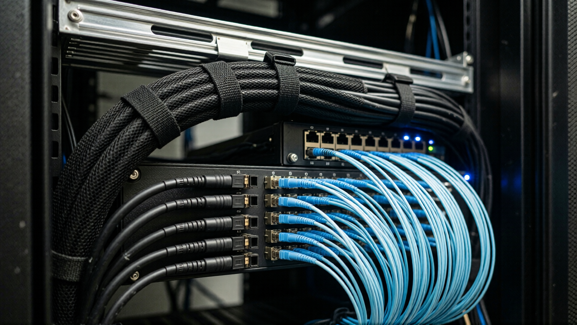
A 96-port CS panel is a marketing number until you try to dress 96 patch cords out of it. Deployable density — the number of ports a technician can actually populate, label, and service — depends on cable management, bend radius, and access angle. Our guide to choosing a fiber patch panel by port density, connector, and cable management sets out the constraints, and the practical rule is blunt: at CS densities, allocate rear and vertical management before you allocate ports. Slim 2.0 mm or 1.6 mm cordage helps, but it does not substitute for structure.
The Efficiency Case: Space, Airflow, and Cost
Space is the visible benefit. There are two quieter ones, and in dense AI-adjacent racks they often matter more.
Airflow and Thermal Interaction
Every patch cord crossing a rack aisle is an obstruction. Halving the cord width per duplex link does not just tidy the front panel; it reduces the physical occlusion in front of switch intakes and, more importantly, it lets a rack carry more ports without adding patching rows that push hot exhaust back toward the intake side. In racks pushing 20 to 40 kW, the difference between a clean 96-port CS field and three stacked LC fields is measurable in intake temperature. The routing and thermal considerations for high-radix optics are covered in our article on 800G and 1.6T optical module thermal and fiber routing design.
Per-Port Cost, Honestly Counted
CS connectors and CS patch cords cost more per unit than their LC equivalents. Any total-cost comparison that stops there is wrong in both directions. The honest comparison includes rack units consumed, panel count, adapter count, jumper length (denser fields allow shorter runs within the row), labelling and documentation labour per port, and the cost of the next rack you do not have to rent. In a build where rack space is the binding constraint, the premium amortizes quickly; in a small enterprise closet with 24 duplex ports total, it never does. CS does not make sense everywhere, and pretending otherwise damages credibility.
Where CS Is the Wrong Choice
CS is a density tool, and density tools are easy to over-apply. Three situations where it usually loses.
- Low port counts. Below roughly 24 duplex ports per rack, the premium on connectors and adapters never pays back, and LC availability and field familiarity win outright.
- Heavy mate cycles at the panel face. Every small-form-factor connector trades some finger access for width. If technicians will be re-patching the same panel daily, evaluate a push-pull variant with a larger boot before committing.
- Pure parallel-optics designs. If the switch port is MPO-native and stays MPO to the far end, inserting CS duplex at an intermediate panel adds conversion points and loss for no density benefit. Keep the link parallel and put the density where the duplex break actually happens.
The underlying engineering standard for the Ethernet layers being patched remains IEEE 802.3, and the current base standard is published through the IEEE Standards Association 802.3 record. The IEC Webstore catalogue at webstore.iec.ch is the reference point for the connector and test-method documents cited above.
The Design Pitfalls That Actually Bite
Half-Seated Connectors and Per-Fiber Loss Measurement
As noted earlier, the dual-ferrule housing can mask a partial mate. Test per fiber, with a light source and power meter or an OLTS configured for single-fiber measurement, and never accept a connector-level pass as evidence that both fibers are good. Certifying a CS field with a duplex-level test is the single most common way to ship a latent fault into production.
Endface Contamination at High Density
Density multiplies contamination opportunities and shrinks the space in which to clean them. A 1.25 mm ferrule endface is inspected and cleaned with the same tooling as LC, and the same acceptance criteria apply — the IEC 61300-3-35 inspection standard, searchable via the IEC Webstore listing for 61300-3-35, defines the zones and defect limits. Our field-facing walkthrough in the fiber optic endface cleaning and inspection guide covers the practical sequence. Budget inspection time per port, not per panel, and treat every CS connector as two endfaces.
Loss Budget and Link Margin
More connectors in a shorter physical span is what high-density patching means in practice. A path that previously crossed two panels may now cross three, and each CS pair contributes insertion loss plus the loss of any adapter or breakout in the chain. Build the budget explicitly rather than assuming headroom; the method and worked examples are in our optical loss budget calculation guide for data center links. For 800G links with tight receiver sensitivity, 0.3 dB of unaccounted loss is the difference between a stable link and an intermittent one.
Specifying the Parts: What to Put on the Purchase Order
A CS deployment is only as good as the bill of materials behind it. The following specification points prevent most of the ambiguity that shows up between a design drawing and a delivered shipment.
- Connector polish and fiber type must be stated per port. APC versus UPC is not interchangeable, and mixing them at a panel is a return-loss disaster. State single-mode or multimode, and state the polish, on every line item.
- Cord diameter and jacket material should be explicit. Slim 1.6 mm or 2.0 mm cordage is what makes CS density usable, but only if the jacket suits the pathway. Where the route crosses a plenum air-handling space, the jacket rating is a code matter, not a preference — see our guide to plenum, riser, and LSZH fiber cable fire ratings.
- Panel density must be paired with a management accessory. Choose the frame, the adapter panel, and the rear or vertical manager as one system. A high-density panel without a matching manager is a field improvisation waiting to happen; the GPX62 extreme high-density panel platform is one example of how those three parts lock together.
- Lengths should be computed, not guessed. Dense fields shorten intra-row runs and lengthen cross-rack runs. Pull the strand count and length model first — the AI rack fiber strand count calculation guide gives the arithmetic.
For the duplex cord itself, the CS product family page is the place to confirm ferrule grade, polish options, and available lengths: CS patch cord assemblies. If the design mixes trunks and duplex fan-out, cross-check the trunk side against MPO versus MTP patch cords so that the breakout ratio and polarity convention are consistent end to end.
A Deployment Sequence That Avoids Rework
- Model the strand count and link topology first. Decide how many duplex paths each rack must terminate, then convert to CS ports and panels. Do not start from a panel SKU.
- Freeze polarity and document it on the drawing. Method A, B, or C, with the pair mapping for every breakout shown explicitly. Ambiguity here surfaces as a failed link months later.
- Verify the optical budget against the worst-case path, including every adapter, breakout, and splice, and hold a defined margin for aging and re-mates.
- Order the panel, adapters, managers, and cordage as a matched set, with jacket ratings appropriate to the pathway.
- Inspect and clean every endface before mating, photographing exceptions. Treat each CS connector as two endfaces, which is exactly what it is.
- Test per fiber and record results per port, not per connector pair, then cross-check against the design labels.
- Dress and label after testing, not before. Labelling a field you are about to re-route wastes a shift. The discipline in our data center fiber cable management guide applies unchanged at CS densities — it simply has less room for error.
Frequently Asked Questions
Is a CS connector compatible with an LC port?
No. CS and LC both use 1.25 mm ferrules, but the housings and latch mechanisms differ and they cannot be mated to one another. A CS patch cord requires a CS adapter or a CS port; an LC port needs an LC connector. The ferrule commonality means test equipment, inspection scopes, and cleaning tools are shared, not that the connectors interoperate.
Does CS support single-mode and multimode?
Yes, in both cases, and with APC and UPC polish options on single-mode. Performance is governed by ferrule grade, polish, and the fiber itself, so a CS link can meet the same insertion loss and return loss targets as an equivalent LC link. The specification on the purchase order should name fiber type and polish explicitly rather than relying on a family name.
How many fibers does one CS connector terminate?
Two — one per ferrule — making it a duplex connector. That is the key architectural difference from MPO, which terminates 8, 12, 16, or more fibers in a single MT ferrule and therefore needs a breakout or trunk strategy rather than a straight duplex mapping.
How much density does CS actually add over LC?
In typical 1RU panels, CS roughly doubles duplex paths: 48 to 72 ports (96 to 144 fibers) versus 24 to 48 ports (48 to 96 fibers) for LC. The exact figure depends on adapter panel design, boot clearance, and rear cable management, so treat vendor density claims as upper bounds and validate against your own cordage and dressing plan.
Can CS be deployed on existing MPO trunk infrastructure?
Yes, and this is the most common migration path. MPO trunks land on the rear of a high-density panel and break out to duplex CS ports on the front, replacing the MPO-to-LC pattern one-for-one. The constraint is polarity: every pair in the breakout must preserve transmit and receive orientation, so the A/B/C convention must be fixed and documented before the panel is specified.
What should be tested on a CS link?
Per-fiber insertion loss and return loss, plus a documented endface inspection against IEC 61300-3-35 criteria before mating. Because the two ferrules are independently sprung, a connector-level pass does not prove both fibers are properly seated — single-fiber measurement is the only way to catch a half-seated pair.
The Practical Conclusion
CS is not a revolution in optical performance. It is a packaging decision that answers a specific constraint: duplex ports per rack unit. Where 400G and 800G optics have pushed a rack to the edge of its patching capacity, CS roughly doubles the front-panel density using ferrules and inspection workflows that technicians already know. Where port counts are modest, or where the link stays parallel end to end, the premium buys nothing and LC or MPO remains the correct answer.
The engineering discipline that makes a CS deployment succeed is unglamorous: model the strand count before choosing a panel, freeze polarity on the drawing, state fiber type and polish on every line item, inspect per endface, and test per fiber. Do those five things and CS behaves exactly like the LC field it replaced, only smaller. Skip them and the density you bought becomes the density that fails.
For teams standardizing across a fleet, the sensible sequencing is to pilot CS on one high-port-count leaf pair, measure deployable density and service time against the LC baseline, and only then write it into the standard. The duplex and simplex patch cord range and the wider duplex patch cord assemblies remain in the catalogue for the links that do not need CS density — a mixed standard is often the honest outcome.