

Short answer: Linear pluggable optics (LPO) are optical modules that keep the analog optical front end but remove the DSP, clock data recovery and retimer from the module, leaving signal equalisation to the host ASIC. That removes a power-hungry and latency-adding stage from every port, but it also removes the margin that used to hide a dirty connector, a reversed polarity pair or a long electrical channel. An LPO link is therefore only as stable as its optical loss budget, its FEC headroom and the inspection discipline applied to every MPO endface in the channel.
What Linear Pluggable Optics Actually Change
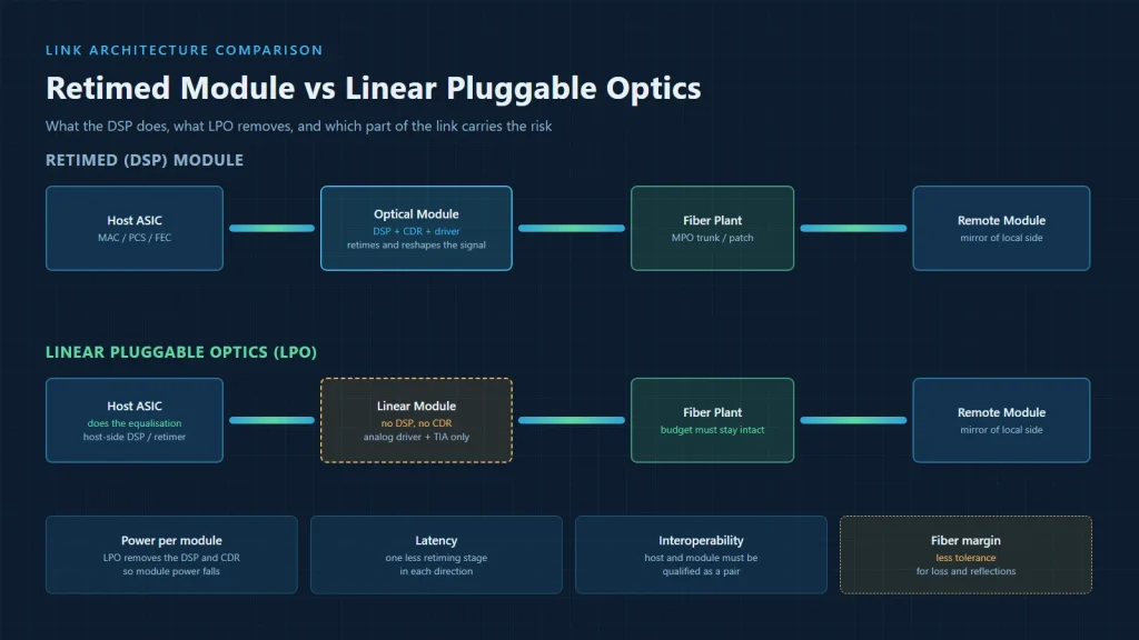
A conventional pluggable module is a self-contained signal regeneration point. Inside the housing sits a DSP that recovers the clock, reshapes the eye, applies its own equalisation and re-encodes the data before handing it to the optical driver. The module therefore repairs whatever the host SerDes and the PCB channel did to the signal, and it does the same in reverse on the receive side. This is why a retimed module can be dropped into a switch with a mediocre host channel and still produce a clean optical eye.
LPO deletes that repair stage. The module contains a linear driver and a transimpedance amplifier, and nothing else that makes decisions about the signal. Equalisation is pushed back to the host ASIC, which must now compensate for both the electrical channel between the ASIC and the module and the linearity limits of the analog optics. The benefit is architectural: fewer active components per port, less power per module, one less retiming stage in each direction, and a shorter signal path overall.
The cost is equally architectural. Everything that the DSP used to absorb becomes visible at the host SerDes and at the FEC layer. A connector that adds half a decibel more loss than expected, a lane with a marginal polish, or a trunk with the wrong polarity no longer produces a link that quietly runs at a slightly higher error rate inside the DSP’s correction window. It produces a link that sits closer to the pre-FEC bit error ratio limit, or one that fails to come up at all. This is the reason LPO discussions in practice spend very little time on the module and a great deal of time on the fiber plant.
Retimed, LPO, LRO and CPO: Where Each One Stops
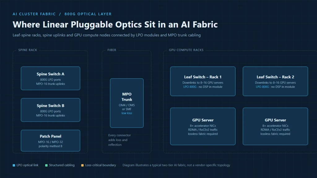
Four architectures are routinely compared, and they differ mainly in how much signal processing lives inside the optics. A retimed module keeps a full DSP. A linear pluggable optical module keeps none. Linear receive optics (LRO) sit in between: the transmit path keeps its DSP while the receive path becomes linear, which halves the power saving but relaxes the host-side receive requirement considerably. Co-packaged optics go further than LPO by removing the pluggable package altogether and placing the optical engine next to the switch ASIC.
| Attribute | Retimed module | LPO | LRO | CPO |
|---|---|---|---|---|
| DSP in the signal path | Transmit and receive | None | Transmit only | Depends on the engine design |
| Module power | Highest | Lowest of the pluggables | Between the two | Lowest per bit, at system level |
| Added latency per hop | One retiming stage each way | None beyond the optics | One way only | Minimal |
| Host SerDes demand | Moderate | High | High on receive | High |
| Interoperability model | Module qualified on its own | Host and module qualified as a pair | Pair, with a narrower scope | Fixed system design |
| Field serviceability | Swap any compliant module | Swap within a qualified pair | Swap within a qualified pair | Not field replaceable at module level |
The table explains why LPO is described as a system-level decision rather than a module purchase. The moment the DSP leaves the module, the module stops being an independent unit that can be qualified alone. What gets qualified is the combination of a specific switch or NIC port, a specific host channel, a specific module and a specific fiber channel length.
The Link Budget Is the Real Constraint
Every optical link is designed against a budget: transmitter output, minus connector and splice loss, minus fiber attenuation, minus a penalty for dispersion and reflections, must still leave the receiver above its sensitivity with margin left over. In a retimed link the margin can be thinner because the DSP recovers a degraded signal. In an LPO link the margin is doing the same job with less help, so the budget has to be built honestly and then verified link by link.
Three terms dominate the calculation in a data center build:
- Connector loss, counted twice per mated pair. A trunk run from a leaf switch to a server NIC typically crosses a switch port, a patch panel at the top of the rack, a second panel or cassette at the server end, and the NIC port. Each mated MPO or LC pair contributes loss, and the count is often higher than the drawing suggests because cable management adds intermediate connections.
- Fiber attenuation over the actual routed length. The routed length is not the straight-line distance between racks. It includes slack loops, cable managers and the vertical run, and multimode attenuation at 850 nm is specified per kilometre, so hundreds of extra metres matter.
- Penalty for reflections and lane imbalance. A parallel link is a group of lanes, and the weakest lane sets the performance of the whole link. One degraded lane in a 16-fiber trunk can push the entire 800G port toward its pre-FEC limit.
The working method is the same one used for any disciplined optical design: calculate the budget first, then measure every installed link, then compare. The step-by-step method with connector, splice and fiber attenuation values is set out in the optical loss budget calculation guide, and the same arithmetic applies to LPO channels with one change: the design margin should be wider, not the same, because the DSP is no longer available to rescue a shortfall.
In LPO deployments the practical rule most teams converge on is to treat the calculated margin as a hard acceptance threshold rather than a target. If a link measures close to the limit during commissioning, it will drift past the limit at the first re-patch, at the first contaminated endface, or after the first thermal cycle in a live rack.
Why FEC and Pre-FEC BER Matter More With LPO
High-speed Ethernet links rely on forward error correction. The 400G and 800G port types defined by IEEE 802.3 use Reed-Solomon FEC with a known correction capability, and the receiver is expected to deliver a pre-FEC bit error ratio below a defined threshold so that the corrected output is effectively error free.
Removing the DSP changes how much of that budget is consumed before FEC even starts. In a retimed link, the module’s internal processing cleans the signal, so the FEC decoder sees a relatively well-conditioned bit stream. In an LPO link the FEC decoder sees the raw result of the host equaliser fighting the optical channel. The correction capability has not changed, but the amount of error it has to remove has.
Two consequences follow. First, link commissioning has to include a pre-FEC BER reading per lane, not just a pass or fail on link-up. A link that trains at 800G with a pre-FEC ratio near the limit will appear healthy in a dashboard and will still produce enough residual errors under load to disturb latency-sensitive traffic. Second, the FEC budget becomes an operational monitoring item. If pre-FEC BER on a production LPO port drifts upward over weeks, the cause is usually physical: an endface that was not cleaned before installation, a connector pair strained by cable weight, or a trunk routed below its minimum bend radius.
This is the reason congestion control tuning documents, such as the RoCE network design guide, keep returning to the physical layer. Lossless RDMA fabric settings assume a link that is not silently retransmitting, and an LPO port with thin FEC headroom violates that assumption before any switch configuration is applied.
Host-Module Interoperability Cannot Be Skipped
Because equalisation moved into the host, an LPO module is only guaranteed to work with a host whose SerDes was tuned for it. The practical implications are specific:
- Qualify the pair, not the part. A module that performs well on one switch family may show a closed eye on another, because host equaliser settings, PCB loss and firmware tuning differ. Vendor interoperability statements are a starting point, not a substitute for a lab run.
- Test the worst channel, not the best one. Evaluate the pair on the longest host channel in the intended design, at the highest ambient temperature the rack will see, and with the module population that will actually be installed.
- Confirm firmware behaviour on link training. Adaptive equalisation is negotiated during link training. If a host firmware update changes that negotiation, previously qualified pairs must be re-verified rather than assumed to be unchanged.
- Keep a documented module allow-list per port type. In a mixed fleet the risk is not a single bad module but an unplanned substitution during a repair.
For teams that also operate RDMA fabrics, the same discipline appears in Understanding RoCE v2: protocol tuning only pays off when the underlying ports behave predictably.
Fiber Plant Rules for LPO Links
Nothing about LPO requires a new fiber type. It requires stricter execution with the fiber types already in use.
Choose the medium for the reach, then stop optimising
Inside a row or between adjacent rows, multimode parallel optics remain the cost-effective choice at 400G and 800G, with OM4 or OM5 supporting the lane counts involved. Once links cross a building, exceed the reach available at the required lane count, or are expected to move to longer reach later, single-mode becomes the simpler decision. The mistake to avoid is designing a multimode channel that sits exactly at its reach limit, then adding a patch panel during construction.
Get polarity right across the whole channel
Polarity errors are the classic cause of a parallel link that passes loss testing and fails to carry traffic. Method A, B and C produce different lane orderings, and the method only works if it is consistent from the switch port to the NIC port, through every cassette and panel. The three methods and their lane mapping are compared in the fiber polarity guide, and the connector-level differences between MPO and MTP bodies are covered in the MPO vs MTP comparison.
Build the backbone from pre-terminated trunk assemblies
Trunk-based backbones are the norm for 800G rack builds because they remove field termination from the critical path. Fiber count, lane mapping, polarity and installation rules for these assemblies are set out in the MPO MTP trunk cable guide. What changes for LPO is the tolerance for a marginal assembly: a trunk that would have been acceptable with a retimed module is a risk with a linear one, so per-lane loss and endface condition should be recorded at installation rather than discovered during commissioning.
Inspect and clean every endface before it enters a port
Contamination is the most common single cause of excess loss in a new build, and it is entirely preventable. The procedure and the inspection criteria are covered in the endface cleaning and inspection guide, and the handling rules that prevent damage during patching are in the MPO/MTP jumper installation tips.
Thermal and Density Consequences at Rack Level
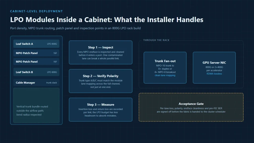
Lower module power changes the rack, not just the module. A switch that no longer has to remove several watts per port can support a higher port population within the same thermal envelope, which is the entire commercial argument for LPO in dense AI racks. But the benefit only materialises if the surrounding infrastructure keeps up.
Three practical effects appear in real builds. Front-panel density rises, which makes connector access tighter and makes endface inspection easier to skip under schedule pressure. Cable bundles become the limiting mechanical factor before the optics do, which is why high-density panels and shuffle solutions exist: an inline shuffle panel such as the GPX78 1RU inline shuffle panel reorganises fiber order in a controlled place instead of at the switch face. And connector formats begin to matter as much as optics: the migration from LC duplex to multi-fiber and MMC formats is driven by exactly this density pressure, as described in From LC to MMC.
For the optical engine side of the same trend, including co-packaged architectures that go beyond LPO, the deployment trade-offs are reviewed in AI data center interconnect 2026 and in the market-level view of co-packaged optics trends.
Migration: Mixing LPO and Retimed Modules
Most data centers will not switch an entire fabric at once. A realistic migration keeps existing retimed links in place and introduces LPO on new leaf-spine or scale-out links. Four rules keep that mixed state manageable:
- Do not mix architectures inside one port group or one LAG. A bundled link whose members have different latency and equalisation behaviour produces unpredictable load distribution, especially with RDMA traffic.
- Keep LPO links inside a known channel class. If a leaf-spine pair is qualified with LPO at one reach and one panel count, do not reuse the same module on a longer run without re-qualifying.
- Label the physical layer, not only the port. Trunk assemblies and patch cords on LPO links should be identifiable at the panel, so that a future repair does not substitute a marginal assembly into a link with the least headroom.
- Track pre-FEC BER as a baseline for every LPO link. The baseline recorded at commissioning is the only reliable reference for judging whether a later drift is environmental, mechanical or optical.
The module-specific choices on the same fabric, including connector and lane-mapping options for high-density ports, are collected in the MPO-ELSFP connector patch cord and MTP MPO trunk assemblies product pages.
Deployment Checklist for an LPO Link
The checklist below is written to be used at commissioning, not at design time. Each item either produces a recorded value or a physical verification step.
- Calculated loss budget exists for the specific channel, including every mated pair, and the design margin is wider than the one used for retimed links.
- Host and module are qualified as a pair on the longest intended channel, at operating temperature.
- Polarity method is confirmed end to end and matches the module lane mapping.
- Every trunk and patch endface is inspected and cleaned before mating; results are recorded per connector, not per link.
- Insertion loss and return loss are measured per lane and compared with the calculated budget.
- Pre-FEC BER is read on every lane after link-up and stored as the commissioning baseline.
- Trunk routing respects bend radius, and cable weight is supported independently of the connector housing.
- Module allow-list and firmware version are recorded against the port type.
- Monitoring thresholds for pre-FEC BER drift and FEC-corrected error counts are configured before handover.
Frequently Asked Questions About LPO
What does LPO stand for and how is it different from a normal optical module?
LPO stands for linear pluggable optics. The difference from a normal retimed module is that the DSP, clock data recovery and retimer are removed from the module, and signal equalisation is performed by the host ASIC instead. The result is lower module power and one less retiming stage in each direction, at the cost of a narrower optical and electrical margin.
Does LPO require a different fiber or different connectors?
No. LPO uses the same multimode and single-mode fibers and the same MPO, MTP, LC or MMC connectors as retimed modules. What changes is the tolerance: connector loss, endface cleanliness and polarity accuracy all consume margin that the module no longer restores, so the same fiber plant has to be built and measured more carefully.
Is LPO the same thing as CPO?
No. LPO keeps the pluggable package and removes the DSP from inside it. Co-packaged optics removes the pluggable package as well, placing the optical engine next to the switch ASIC. LPO is a drop-in change to a port; CPO changes the system architecture and the service model.
Can LPO and retimed modules be used in the same switch?
Usually yes, at the port level, provided each port is qualified for the module installed in it. They should not be mixed inside a single link aggregation group, because different equalisation and latency behaviour across members of the same bundle makes traffic distribution and RDMA tuning unpredictable.
Why does an LPO link pass loss testing but fail to carry traffic?
In most cases the failure is not loss but lane order or endface condition. A polarity mismatch produces a link that measures correctly and cannot pass data, and a contaminated connector produces per-lane errors that only appear once FEC statistics are read. Checking pre-FEC BER per lane and verifying polarity end to end resolves the majority of these cases.
Standards and Reference Material
Ethernet port types, FEC and channel specifications are maintained by IEEE 802.3. Multi-fiber connector interfaces and their dimensional requirements are defined in the IEC 61754 series, with the MPO interface published by the International Electrotechnical Commission. Fibre attenuation, dispersion and macrobend figures used in a link budget come from the recommendations maintained by ITU-T.
Linear pluggable links are only as good as the passive layer beneath them. The MTP/MPO selection framework for AI data centers explains how connector grade and mated-pair counts set the loss budget a linear module has to live with.