

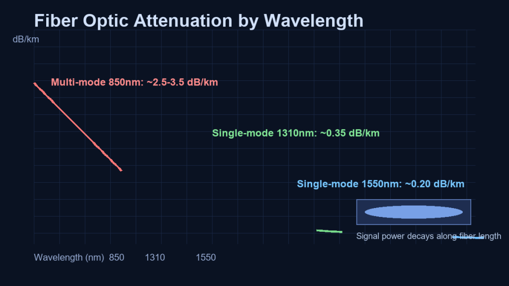
Short answer: Fiber optic attenuation is the loss of optical signal power along a fiber, measured in dB/km. It comes from material absorption, Rayleigh scattering, macro/micro-bending, and connector or splice loss. You reduce it by choosing the right fiber type (OS2 single-mode for long reach, OM4/OM5 for data center links), respecting bend radius and tension during installation, and keeping connector endfaces clean.
What Is Fiber Optic Attenuation?
Fiber optic attenuation is the gradual loss of optical signal power as light travels through a fiber. It is measured in decibels per kilometer (dB/km) and is one of the most important parameters in optical network design, because it directly determines how far a signal can travel before amplification or regeneration is needed. Lower attenuation means longer reach, fewer amplifiers, and simpler link budgets for data centers, campus networks, and telecom backbones.
Attenuation is a natural physical property of every optical fiber. No cable is perfectly transparent: some of the light energy is absorbed by the glass material, some is scattered by microscopic impurities, and some is lost when the fiber is bent beyond its safe radius. Understanding where the loss comes from helps engineers select the right fiber and patch cord, connectors, and installation practices for each link.
Common Causes of Attenuation in Optical Fiber
Optical loss in a fiber link comes from several sources, and each one can be controlled with the right product and installation choices:
- Material absorption: impurities in the glass absorb light energy and convert it to heat. Modern fiber manufacturing minimizes these impurities, which is why today’s standard single-mode fiber achieves very low attenuation in the operating windows.
- Rayleigh scattering: microscopic density fluctuations in the glass scatter light in all directions. A small fraction of the light is scattered away from the core and lost. This is the fundamental limit that sets the minimum attenuation of a given fiber design.
- Macro-bending: sharp bends in the cable push light out of the core and into the cladding. Bending the fiber below its minimum bend radius causes significant loss, which is why bend-insensitive fiber and proper cable routing matter in tight spaces.
- Micro-bending: small local deformations of the fiber, often caused by excessive cable tension or tight cable ties, also couple light out of the core. Good cable management and proper tension control prevent this.
- Connector and splice loss: every mated connector pair and fusion splice adds a small amount of insertion loss. High-quality connectors with precise ferrule alignment keep this contribution low and stable. See our guide to physical contact in fiber connector ferrules for what happens at the mating interface.
How Attenuation Is Measured
Attenuation is measured with an optical time-domain reflectometer (OTDR) or a light source and power meter. An OTDR sends pulses into the fiber and measures the light that is back-scattered along the length, producing a trace that shows loss at every splice, connector, and bend. This makes it the standard tool for certifying installed links and locating faults.
The unit dB/km expresses how much power is lost per kilometer of fiber at a given wavelength. Because different wavelengths interact differently with the glass, the same fiber shows different attenuation values at different wavelengths.
Typical Attenuation Values for Common Fiber Types
| Fiber type | Operating window | Typical attenuation (dB/km) | Common application |
|---|---|---|---|
| Single-mode OS1/OS2 (9/125) | 1310 nm | 0.32 – 0.40 | Long-haul, metro, data center interconnect |
| Single-mode OS1/OS2 (9/125) | 1550 nm | 0.18 – 0.25 | Long-haul, DWDM, access |
| Multi-mode OM3 (50/125) | 850 nm | 2.5 – 3.5 | Data center parallel optics, 40G/100G SR |
| Multi-mode OM4 (50/125) | 850 nm | 2.5 – 3.5 | Data center, 100G/400G SR8/SR4 |
| Multi-mode OM5 (50/125) | 850/953 nm | 2.5 – 3.5 | Short wavelength division multiplexing |
These values are typical ranges rather than fixed numbers; always refer to the datasheet of the specific cable for the guaranteed specification. The reach of each fiber class is also limited by modal dispersion and transceiver budgets — our patch cord selection guide explains how core size and wavelength interact.
Standard single-mode fiber specifications are defined by the IEC 60793 series (IEC) and the ITU-T G.652 recommendation (ITU-T), which set the attenuation limits used in datasheets and link engineering.
How to Reduce Fiber Attenuation
Attenuation is controlled first at the product level and then at the installation level. On the product side, choose fiber with a specification that matches the link reach: OS1/OS2 single-mode for long distances, OM3/OM4/OM5 multi-mode for short data-center links. Use bend-insensitive fiber where tight routing is unavoidable, and select connectors with low insertion loss and stable return loss.
On the installation side, respect the minimum bend radius of the cable, avoid excessive tension during pulling, keep cable ties loose enough not to crush the jacket, and use proper cable management in patch panels and ODFs. Clean every connector endface before mating and re-test after any reconfiguration, because contamination is one of the most common causes of unexpected link loss.
At the system level, attenuation budgets interact with the same high-density cabling choices that decide whether an AI-scale fabric works at all. Our articles on optical interconnect in AI infrastructure and high-density fiber deployment best practices show how loss, density, and reach fit together. If your design uses parallel optics, also review MPO vs MTP connector selection and fiber polarity management, since connector loss and polarity errors both eat into the link budget.
Frequently Asked Questions
Is lower attenuation always better?
Lower attenuation is better for reach and link margin, but fiber is chosen as a system: multi-mode fiber has higher attenuation than single-mode, yet it is the right choice for short data-center links because transceivers are less expensive and installation is simpler. Match the fiber type to the distance and the transceiver standard.
Why does attenuation increase with distance?
Because the loss is distributed along the fiber: every kilometer contributes a fixed amount of loss at the operating wavelength. A 10 km link at 0.4 dB/km adds 4 dB of fiber loss, before connectors and splices are counted.
How do I know if my link loss is acceptable?
Compare the measured end-to-end loss with the link budget: the sum of fiber loss, connector loss, splice loss, and margin must stay below the power budget of the transceivers. An OTDR trace shows where each loss element sits, making it easy to identify the element that exceeds the budget. Browse our pre-terminated trunk solutions and the fiber optic product series for components with controlled, datasheet-guaranteed loss.