


Short answer: A RoCE network is an Ethernet fabric that carries RDMA traffic directly over IP, and its performance is decided less by the switch than by the physical layer beneath it. To build a working RoCE network you need a lossless Layer 2 path (PFC and ECN enabled), a fiber plant that stays inside a calculated optical loss budget, polarity that is correct on every multi-fiber link, and connector endfaces that are clean and inspected before the first frame is sent. Most RoCE network instability traced in the field comes from dirty or mis-polarized multi-fiber connectors, not from the protocol stack.
What Is a RoCE Network and Why the Physical Layer Decides Its Performance
RoCE, RDMA over Converged Ethernet, moves remote direct memory access semantics onto Ethernet so that servers can read and write each other’s memory without involving the CPU. RoCE v2 encapsulates the RDMA payload in UDP/IP, which makes it routable across Layer 3 boundaries. That routability is the reason AI clusters and storage fabrics adopt it: the same switch family carries management, storage, and accelerator traffic instead of maintaining a separate InfiniBand fabric.
The price of that convergence is sensitivity. RDMA assumes the network behaves close to ideally: near-zero packet loss, stable latency, and in-order delivery. Ethernet was not designed that way, so engineers compensate with Priority Flow Control, Explicit Congestion Notification, and careful traffic marking. All of that compensation assumes the link itself is healthy. A marginal optical connector or a reversed polarity pair will generate a small but persistent error rate that PFC cannot absorb, and the fabric reacts by pausing traffic, which shows up as latency spikes under load rather than as a clean link-down alarm.
If you are new to the protocol itself, the mechanics of queue pairs, memory registration, and the v1 versus v2 distinction are covered in Understanding RoCE v2. This guide looks at the layer most deployment documents skip: the fiber, the connectors, and the physical budget between them.
RoCE v2 and the Lossless Ethernet Requirements That Reach the Cabling
Lossless operation is usually described as a configuration task, but three of its inputs are physical:
- Link error rate. Pre-FEC bit error ratio on a marginal multimode or dirty single-mode link can sit just under the threshold that triggers link flapping, while still forcing enough retransmission to break RDMA’s latency assumptions.
- Asymmetric loss between lanes. A 400G or 800G parallel link is several lanes in one jacket. If one lane runs 2 dB hotter than the others because of a damaged ferrule or a poorly seated guide pin, the module still links but degrades under temperature swing.
- Insertion loss repeatability. Every re-mate of a multi-fiber connector adds a small random loss step. Cabling designed with no headroom is stable in the lab and unstable after the third maintenance window.
Treat loss budget as a design constraint rather than a post-installation measurement. The step-by-step method, including connector, splice, and fiber attenuation values, is documented in the optical loss budget calculation guide for data center fiber links.
Calculating a Link Budget That Survives Real Maintenance
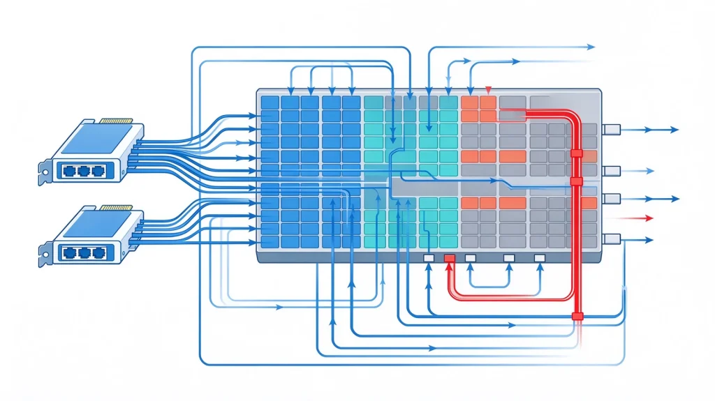
A practical RoCE network link budget subtracts the following from the transceiver’s specified budget: fiber attenuation at the operating wavelength, connector loss per mated pair, splice loss if any, and a maintenance margin. For short-reach multimode links inside a row, fiber attenuation is almost irrelevant and connector loss dominates. For single-mode links across a campus or between buildings, fiber attenuation at 1310 nm becomes the leading term and the connector count matters less.
Two habits keep budgets honest. First, count every mated pair, including patch panels and the adapter at the NIC; a spine-to-leaf path with two patch panels frequently carries six mated pairs, not two. Second, specify a maintenance margin of at least 1 dB on multimode and 2 dB on longer single-mode runs, so that re-mating and cleaning do not consume the entire reserve. The underlying physics of excess loss and how to measure it is covered in fiber optic attenuation: causes, measurement, and how to reduce it.
Connector and Polarity Choices for RoCE Spine-Leaf Cabling
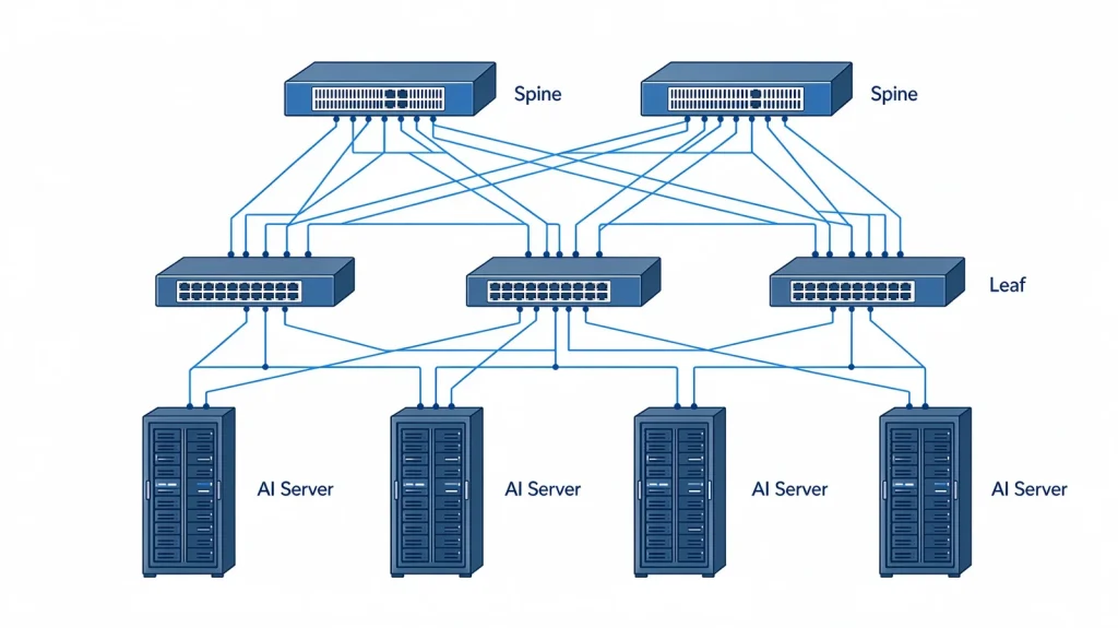
RoCE fabrics are typically built as a two-tier spine-leaf topology with parallel optics at the server edge and higher-lane-count links in the spine. That produces three distinct cabling problems in one network:
Server edge. 400G and 800G ports break out into 8 or 16 lanes, which means multi-fiber connectors at high density. The choice between connector families changes rack space more than it changes optical performance; the trade-offs are set out in MPO vs MTP patch cords.
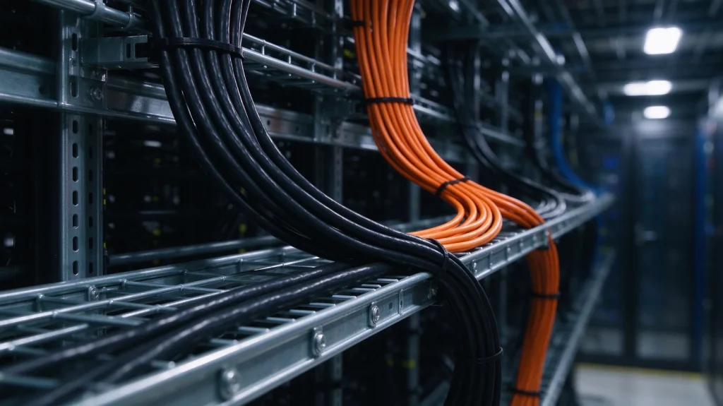
Structured cabling between rows. Trunk assemblies terminate into patch panels, and every transition is a mated pair that must be accounted for in the budget and in polarity planning.
Module architecture at the edge. If the ports on either side of that channel are linear pluggable optics, the same cable run has to be built with less margin, because nothing inside the module restores the signal. The design rules for that case, including link budget and FEC headroom, are set out in the LPO deployment guide for 800G AI fabrics.
Polarity. Parallel optics require a defined transmit-to-receive mapping end to end. Method B (key-up to key-down) is the common choice for parallel links, but the method must be consistent across the entire channel, including panels and cassettes. A single crossover in the middle of a Method B channel produces a link that lights but never passes traffic. The three methods and their failure modes are explained in the fiber polarity guide for methods A, B, and C.
Fiber Count and Rack Density Planning
RoCE network designs fail at the rack level more often than at the protocol level. A single AI rack with eight accelerators and a pair of leaf switches can consume well over a hundred fibers once breakouts, redundancy, and storage ports are counted. Sizing this correctly before the cable schedule is issued avoids the common outcome of adding panels and jumpers after the racks are already populated.
A worked calculation, including how oversubscription ratios and breakout configurations change the strand count, is available in how many fiber strands an AI rack needs. For rack-level physical layout, including power shelves and cable management zones, see the OCP ORv3 rack architecture reference, and for the wider connectivity picture, the AI data center optical connectivity solutions overview.
Where Latency Actually Comes From in a RoCE Network
Engineers often assume the cable is latency-neutral and therefore ignore it. That is true for propagation delay in short runs, but not true for the optics and for the retransmission behaviour caused by marginal links.
Optical module architecture matters here. Linear-drive optics remove the DSP from the module and rely on the host to equalize the link, which reduces per-hop latency and power. That trade-off changes the host-side tuning requirements and the tolerance to loss: a link with less digital compensation has less room for a degraded connector. The architecture and its implications are described in linear-drive optical (LPO) modules. For module class selection at 800G, including reach and form factor comparisons, see the 800G optical module selection guide.
The larger latency contributor in practice is congestion response. When a link degrades, PFC pause frames propagate through the fabric and the tail latency of unrelated flows rises. Fixing the connector is usually faster than retuning the congestion control.
Cleaning and Inspection Before the Fabric Goes Live
Contamination is the single most common physical cause of RoCE network instability. A multi-fiber connector presents 12, 16, or 24 endfaces at once, and a single contaminated fiber in the array degrades one lane while the link stays up. Inspection at every mated interface before first traffic, and again after any re-mating, is the only reliable control.
Use a scope with automated pass/fail against the relevant acceptance criteria rather than visual judgement, and clean with a method appropriate to the connector type. The workflow, including what to do when a connector fails inspection repeatedly, is set out in the fiber endface cleaning and inspection guide.
Deployment Checklist for a RoCE Network Build
- Confirm the loss budget per link class, including every mated pair and a maintenance margin.
- Fix the polarity method per channel and verify it through panels and cassettes, not only at the endpoints.
- Size strand count from the rack design, not from the switch port count alone.
- Inspect and clean every multi-fiber interface before first traffic; record results.
- Enable PFC and ECN, then verify that pause counters stay near zero under synthetic load.
- Re-baseline insertion loss after the first maintenance window, since re-mating changes loss.
Panel and connector selection for the structured part of the build is covered in how to choose a fiber patch panel.
Frequently Asked Questions About RoCE Networks
Is a RoCE network the same as standard Ethernet?
Physically yes, and that is the point. A RoCE network runs on standard Ethernet switches, optics, and cabling. What differs is the configuration discipline: lossless behaviour has to be engineered with PFC and ECN, and the physical layer has to be clean enough that the fabric does not spend its time recovering from errors.
Can I run RoCE over existing multimode fiber?
Yes for short-reach links inside a row or between adjacent rows. The constraints are the reach rating of the transceiver, the loss budget including all mated pairs, and the quality of the existing connectors. Legacy connectors that fail inspection should be replaced rather than cleaned repeatedly, because repeated cleaning of a damaged ferrule removes material and worsens loss.
What causes RoCE network latency spikes that look unrelated to traffic?
Usually a marginal physical link. A lane running near its error threshold triggers retransmission and PFC pauses, and because pause frames propagate, flows on other ports slow down too. Checking pre-FEC error counters per lane, then inspecting and re-mating the affected connector, resolves the majority of these cases.
Do I need single-mode or multimode optics for a RoCE fabric?
It depends on reach and on lane count. Multimode with parallel optics is cost-effective inside a row or between adjacent rows at 400G and 800G. Single-mode becomes preferable when links cross a building, when reach exceeds multimode limits at the required lane count, or when future upgrades to longer reach are likely.
How does cabling affect congestion control tuning?
A clean link gives congestion control room to work with conservative settings. A marginal link forces aggressive PFC thresholds that in turn create head-of-line blocking and unfairness. Fixing the physical layer usually allows simpler, more stable congestion settings than tuning around a degraded link.
Standards and Reference Material
Physical layer requirements for Ethernet are maintained by IEEE 802.3. RDMA architecture and compliance programmes are published by the InfiniBand Trade Association. Optical interface agreements relevant to high-speed module interoperation are published by the Optical Internetworking Forum.