
FAU Selection Is About More Than Channel Count: Why Chip Interfaces and Fiber Parameters Matter
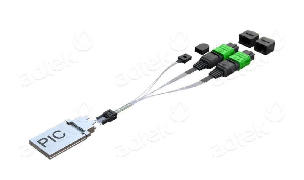
As optical interconnect technologies continue to evolve, driven by developments in optical engines and co-packaged optics (CPO), the way optical fibers connect to chips is also changing. The Fiber Array Unit (FAU), a key component for precisely arranging and connecting multiple optical fibers, is attracting increasing attention across the industry.
When evaluating an FAU, channel count is often the most obvious parameter. Whether it is a 12-channel, 16-channel, or 32-channel unit, a higher number may appear to offer greater optical connectivity capacity. In practice, however, channel count is only the starting point for selection, not the sole criterion for determining suitability.
Even when two FAUs have the same channel count, they may not be interchangeable if they differ in chip coupling method, such as edge coupling or vertical coupling, array pitch, or assembly method, such as adhesive bonding or pluggable integration.
So, what factors should be considered when selecting an FAU?
01. Why Aren’t FAUs with the Same Channel Count Always Interchangeable?
An FAU can be understood as a precision unit for arranging and connecting optical fibers.
It holds multiple fibers in a defined configuration, positioning each fiber so that it can establish an optical connection with a target optical component at a predetermined location.
Two requirements are essential: accurate fiber alignment and interface compatibility.
Channel count answers the question, “How many fibers need to be arranged?” It does not fully answer several other important questions:
Where must each fiber be positioned?
How should the fibers couple optically to the chip?
Do the selected fibers meet the system’s transmission requirements?
How will the fiber array be integrated into the overall system?
Together, these factors determine whether an FAU is suitable for a particular application.
An FAU is therefore more than a collection of fibers arranged side by side. It is a precision component that must meet a combination of mechanical, optical, manufacturing, assembly, and reliability requirements.
02. Chip Interfaces: Where Do the Fibers Need to Connect?
The first consideration in FAU selection is the interface design of the target chip.
In applications involving optical engines or CPO, the fiber array must establish a precise optical connection with the chip or its associated optical structures. Different interface designs may impose different requirements on fiber arrangement, end-face positioning, and coupling methods.
Three aspects deserve particular attention.
1. Fiber Array Pitch
The spacing between adjacent fibers is commonly referred to as the pitch.
If the chip interface requires fibers to be arranged at a specific pitch, the FAU must be designed to match that requirement. Even if two products have the same channel count, different fiber spacing may prevent them from aligning correctly with the target interface.
For example, two 16-channel FAUs may have exactly the same number of channels. However, if their fiber pitches differ, they cannot be considered interchangeable based on channel count alone.
2. Interface Structure and Coupling Method
There is more than one way to establish an optical connection between a fiber and a chip.
Depending on the design, optical signals may be coupled through different types of optical interfaces. Each approach may impose specific requirements on the FAU’s structure, end-face design, positioning features, and the relative alignment between the fibers and the chip.
During selection, it is therefore important to identify not only the required channel count, but also the target chip interface and how the FAU is expected to mate with it.
3. Alignment Accuracy
Optical coupling efficiency is closely related to the relative positioning of the fiber and the target optical structure.
Positional deviations can increase optical coupling loss and affect the performance of the overall optical link.
In multi-channel applications, alignment accuracy must be considered across the entire array, rather than for just one individual fiber. Consistent fiber positioning and array geometry are therefore essential.
This is why FAU design and manufacturing must account for dimensional accuracy, positional accuracy, and assembly consistency.
In simple terms, the chip interface determines how and where the fibers need to connect. The FAU must be designed to accommodate those requirements.
03. Fiber Parameters: It’s Not Enough to Align the Fibers—They Must Also Meet Transmission Requirements
If the chip interface determines how the fibers connect, fiber parameters help determine whether the optical signals can be transmitted as required by the system.
Several parameters deserve particular attention when selecting an FAU.
1. Fiber Type
Different applications may require different fiber types.
For example, single-mode fiber and multimode fiber have different transmission characteristics and are suited to different applications. Similar external dimensions do not mean that the two types can be used interchangeably.
In high-speed optical interconnect applications, the appropriate fiber type should be selected according to the system’s optical design, transmission distance, operating wavelength, and other relevant requirements.
2. Mode Field Diameter
For single-mode fiber, mode field diameter (MFD) is an important parameter.
MFD describes the effective spatial extent of the optical mode propagating through the fiber. It is not the same as the fiber’s physical diameter.
When light is coupled between a fiber and a chip or another optical component, the compatibility of their optical mode profiles can affect how efficiently optical power is transferred. Consequently, fibers with the same external dimensions cannot automatically be assumed to have identical optical characteristics.
The appropriate MFD specification should be determined according to the optical design and interface requirements of the target device.
3. Fiber Cladding Diameter and Array Geometry
Fiber cladding diameter is one of the factors that influence fiber array design.
In a multi-channel FAU, fibers must be arranged and secured at predetermined positions. Cladding dimensions, fiber arrangement, and the associated structural design all affect how the array can be implemented.
It is important to note that cladding diameter is not the same as fiber pitch. The actual pitch depends on several factors, including the array design, V-groove geometry, fiber dimensional tolerances, and manufacturing process control.
For this reason, FAU selection should involve checking both fiber specifications and array geometry rather than confirming only one of them.
4. Operating Wavelength and Optical Performance Requirements
Fiber and optical component performance must be evaluated at the intended operating wavelength.
Transmission characteristics, mode field distribution, and coupling performance may vary under different wavelength conditions.
For an FAU, it is therefore necessary to consider not only the fiber specifications themselves, but also the requirements for the overall optical connection, including insertion loss and return loss.
The applicable performance limits should be defined according to the intended application and system design. A product should not be judged suitable or unsuitable solely by comparing it with a generic specification value.
Ultimately, fiber parameters are not an isolated set of specifications. They must be evaluated together with the chip interface, optical design, and intended application.
04. From Parameters to Applications: FAU Selection Requires a System-Level Assessment
In practical projects, FAU selection generally involves evaluating multiple parameters together.
The following five dimensions provide a useful framework:
| Selection Dimension | Key Considerations | Main Objective |
|---|---|---|
| Channel Configuration | Channel count and channel arrangement | Confirm the required number of fibers and overall array configuration |
| Chip Interface | Interface structure, array pitch, and coupling method | Ensure compatibility with the connection and alignment requirements |
| Fiber Specifications | Fiber type, MFD, cladding diameter, and operating wavelength | Verify compatibility between the fibers and the optical system |
| Assembly Method | Adhesive-bonded assembly or pluggable assembly | Determine the appropriate structure for the fiber array and its integration |
| Performance and Manufacturing | Insertion loss, return loss, positional accuracy, and end-face quality | Verify that the product can meet the application’s performance requirements |
These five dimensions are closely interconnected.
For example, channel count influences the overall array layout. The layout must satisfy the spatial requirements of the chip interface. Fiber type and mode field characteristics affect the optical coupling design, while manufacturing and assembly processes determine whether the intended specifications can be achieved consistently.
FAU selection is therefore not simply a matter of finding a product with matching individual parameters. The goal is to confirm that the complete optical interconnect solution meets the system’s requirements.
For projects still in the design phase, defining the interface specifications, fiber requirements, and key performance targets early can help reduce subsequent design changes and validation costs.
For projects with an established chip interface, selection should begin with the interface specification, followed by the necessary testing and validation to confirm actual product performance.
05. What Matters Most Is Not the Number of Specifications, but How Accurately They Match
As optical interconnect technologies move toward higher density and greater bandwidth, connections between optical fibers and chips are becoming increasingly precise.
The value of an FAU lies not only in arranging multiple fibers at a defined pitch, but also in providing the connection conditions required by the system’s optical design.
Channel count determines the size of the array. The chip interface defines the connection method. Fiber parameters influence optical compatibility, while manufacturing processes determine whether the design requirements can be realized accurately and consistently.
Together, these factors form the foundation of effective FAU selection.
In engineering applications, the most suitable FAU is not necessarily the one with the highest channel count. It is the one that accurately matches the target chip, fiber specifications, and system performance requirements.
Understanding this distinction helps move FAU selection beyond simple specification comparisons toward a more complete understanding of the optical interconnect solution.
06. Every Connection, Backed by Precision
ADTEK continues to follow developments in fiber optic interconnect technology and explore the possibilities of FAU and related products in applications that demand greater density and precision.
We believe that the value of technology is reflected not only in the numbers on a specification sheet, but also in whether every detail can withstand validation and every connection meets the real requirements of the system.
Related articles
Share the page:
Contact US
If you want to know more about us, you can fill out the form to contact us and we will answer your questions at any time.