
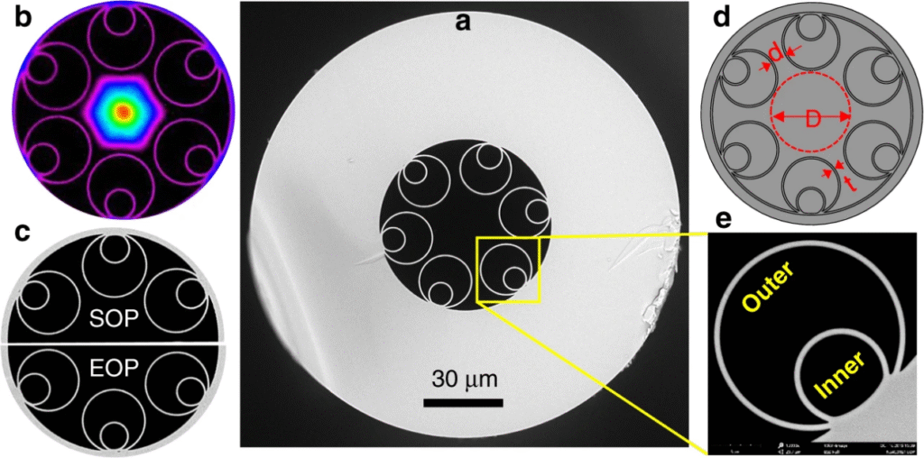
Figure 1: Hollow-core fiber design. (a) Schematic of a tubular anti-resonant HCF: light is confined in a central air core surrounded by thin nested glass capillaries. (b) Conventional single-mode fiber uses a solid glass core. The HCF core and cladding geometry (e.g. honeycomb-like rings of glass) causes light to bounce back into the air channel via photonic-bandgap or anti-resonant effects
Hollow-core fiber (HCF) replaces the glass core of conventional single-mode fiber (SMF) with an air-filled center. In practice HCF is built as a microstructured glass “jacket” surrounding a central air channel. Light is guided not by total internal reflection in glass but by photonic-bandgap or anti-resonant effects in the cladding. Figure 1 shows a common “revolver” anti-resonant design: a central air core with a ring of thin silica tubes. This leaves >99% of the optical mode in air, dramatically reducing interaction with glass. By contrast, an SMF has a solid Ge-doped silica core (∼9 μm diameter) within a lower-index glass cladding. Because the HCF core index (n≈1) is much lower than the cladding, special cladding structures are required to confine light.
Conventional SMF has extremely low loss in the C-band (around 0.2 dB/km). For example, Corning SMF-28 ULL fiber is specified <0.16 dB/km at 1550 nm. In practice high-quality SMF spans 0.16–0.2 dB/km at 1550 nm. In comparison, early HCF prototypes had losses in the 1–10 dB/km range. Thanks to advances (nested anti-resonant designs, “revolver” HCF, etc.), HCF loss has plummeted: from ~1.3 dB/km (2018) to ~0.65 dB/km (2019) to ~0.28 dB/km (2020). Modern designs approach SMF levels: recent demonstrations report HCF loss falling below 0.2 dB/km, and lab prototypes have achieved ~0.11 dB/km. In short-reach datacenter links (tens of km), even 0.2–0.3 dB/km is acceptable, so HCF is nearing practical loss parity.
Attenuation benchmark: SMF (1550 nm) ≈0.16–0.2 dB/km; HCF (current) ≲0.2–0.3 dB/km (targeting ~0.1 dB/km).
The practical implication is that straight-through HCF links can span similar distances as SMF without repeater amplifiers. Because HCF avoids the glass core, its remaining loss is mainly leakage and surface scattering. Notably, as Rayleigh scattering is negligible in air, further loss reductions are possible by refining the anti-resonant structure. The net effect is that well-engineered HCF can rival conventional fiber on attenuation, at least over short to moderate distances.
Because HCF guides light in air, its effective refractive index is near 1 (vs ~1.47 in glass). This means light travels significantly faster in HCF. In practice HCF reduces propagation delay by roughly 30–50%. For example, SMF has group delay ~2.0 µs/km, whereas published HCF designs show ~1.54 µs/km. In other words, an HCF link is ~31% lower latency per km. Figures 2a–b illustrates this speedup. (Note: some sources quote up to ~47% speed increase, depending on precise index differences.)
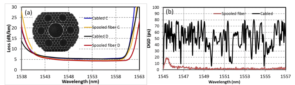
Figure 2: Speed advantage of hollow-core fiber. In air-core HCF (right), optical pulses propagate with ~50% higher velocity than in glass-core SMF (left). This yields about ~30–50% lower group delay (latency) per unit length. The diagram indicates that an HCF link can transmit the same data in roughly two-thirds the time of SMF.In practical terms, a 10 km HCF link would incur ~15 µs propagation delay (5 ns/m) versus ~20 µs in SMF, saving ~5 µs end-to-end. OFS measurements confirm ~1.54 µs/km for HCF vs ~2.24 µs/km for SMF (≈31% reduction). This latency saving is critical for AI/HPC data exchange and high-frequency trading. Indeed, industry tests consistently report ~30% latency improvement. (In a recent Madrid trial, a 1.386 km HCF link shaved 4.287 µs off the round-trip delay relative to SMF.) In summary:
Latency benchmark:SMF ≈2.0 µs/km; HCF ≈1.5–1.6 µs/km, i.e. ~30–35% less delay.
This “speed-of-light” advantage lets datacenters be spaced farther apart for a given latency budget. Equally, within a single DC or campus, HCF links dramatically reduce hop delays, which can help meet sub-microsecond end-to-end requirements of distributed AI trains.
HCF inherits very low dispersion. Because the bulk of light is in air, material dispersion (differing glass refractive index with wavelength) is negligible. Well-designed anti-resonant HCFs show near-zero chromatic dispersion over their low-loss bands. In practice this means pulses broaden very little, improving bandwidth-distance product. Similarly, polarization mode dispersion (PMD) in HCF is minimal, and environmental effects (temperature, stress) have less impact. By contrast, SMF has ~17 ps/(nm·km) chromatic dispersion at 1550 nm (with further variation across C/L band) and PMD on the order of 0.05–0.2 ps/√km in high-end fiber.
Nonlinear effects (Kerr nonlinearity, SPM/XPM, four-wave mixing, etc.) are orders-of-magnitude weaker in HCF. Over 99.99% of the mode is in air, so the effective nonlinear coefficient is ≈100–1000× smaller than in silica. This means HCF can support much higher optical power before nonlinear distortions set in, which in turn can enable higher spectral efficiency per channel or simpler modulation formats. It also yields enhanced security (easier to eavesdrop or inject by fiber tapping) as some proponents note.
Overall, dispersion-related bandwidth limits and nonlinearity constraints are far reduced in HCF. Datacenters can exploit broader wavelength bands (beyond standard C-band) for high-capacity links without needing dispersion compensation. The broad “first antiresonant window” of many HCF designs covers much of 1.5–1.6 µm with flat loss, and second windows can extend into L-band or even visible wavelengths with low loss. In sum, the bandwidth potential of HCF is at least as large as SMF and potentially larger, especially when multi-band operation and high launch powers are considered.
HCF’s high speed and low nonlinearity translate into exceptional capacity. By analogy, HCF is like a wider-lane, higher-speed highway for light: it can carry more “cars” (bits) moving faster. Figure 3 (right) illustrates this: a single HCF “super-van” can carry more data at higher speed than an SMF “car”. In practice, HCF has demonstrated very high aggregate data rates in lab trials. For example, trials have achieved 800 Gb/s and 1.2 Tb/s channels in antiresonant HCF with coherent WDM. In real networks, HCF has supported 6×100 Gb/s lanes on one fiber and similar multi-wavelength loads.
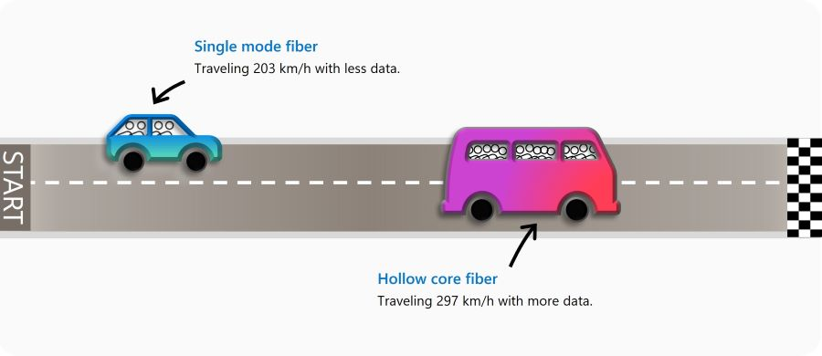
Figure 3: Data throughput analogy. HCF can act like a high-capacity “van” traveling faster, versus SMF as a “car.” This reflects HCF’s combination of high bandwidth (more wavelengths/modes with low distortion) and higher propagation speed. Unlike SMF (left), HCF avoids glass nonlinearities and can use broader spectral windows, enabling >Tb/s on a single fiber.
Key points on HCF capacity:
In summary, HCF offers at least the same potential bandwidth as SMF and, in multi-channel links, can often exceed it through higher launch power and lower crosstalk. The only caveat is that many HCF types have a finite low-loss window, so full fiber C+L+U band use may require multiple fiber types or optimized dispersion-engineered designs.
While HCF’s physics are promising, several engineering challenges remain:
In summary, practical HCF links today may require careful handling: fusion spliced assemblies , large slack loops, and specialized cables. The industry is actively developing standards and best practices. For example, OFS AccuCore™ cables are now offered for HCF with standard form factors. However, every HCF link still incurs roughly 0.5–3 dB of extra loss for cabling/splices, limiting reach and necessitating power budgeting.
HCF is already moving out of the lab into real networks. Recent field trials and pilot deployments show promising results:
In all these trials, performances met expectations: significant latency drops (typically ~30%) and multi-hundred-Gbps capacities on short links. However, none of these trials yet extend HCF hundreds of km – that remains future work. For now, HCF is best suited to metro-scale or intra-datacenter links (up to ~10–20 km), where its benefits shine without requiring active repeaters.
The push toward AI and ultra-fast HPC is heightening demand for ultra-low-latency, ultra-high-bandwidth links. HCF is uniquely positioned to address these needs. By reducing link delay ~30% per km, HCF lets DC operators stretch geographic coverage: analyses suggest data centers could be placed 1.5× farther apart for the same latency. This “geographic flexibility” can be crucial as AI clusters span multiple sites. Likewise, within a data center, HCF can cut inter-rack and inter-pod latencies, feeding large models with minimal data transfer lag.
Beyond raw speed, HCF’s low nonlinearity and broad spectrum support mean future transceivers can push data rates even higher. Combined with advanced modulation and parallel fiber schemes (e.g. multicore HCF), the overall throughput could greatly exceed today’s SMF links. Providers envision HCF carrying terabit-per-second traffic per strand in the next decade, meeting the exascale I/O needs of AI chips.
Industry is taking notice. Major cloud/HPC players (Microsoft, Google, Meta) have funded HCF R&D or acquisitions, and startups (Relativity, Lumenisity) have secured millions in venture and government backing. Standards bodies and consortia are beginning to include HCF in future network plans. While many uncertainties remain (cost, reliability, integration), the trend is clear: HCF is on track to become a key building block for next-generation low-latency, high-capacity datacenter networks.
In conclusion, hollow-core fiber represents a compelling advancement for data-center optics. By swapping glass for air, it cuts loss and latency while expanding bandwidth and linearity. Early trials prove its viability, and ongoing developments are rapidly overcoming practical hurdles. For AI and HPC deployments that demand “light-speed” networking, HCF offers an unmatched path forward – provided its remaining engineering and cost challenges can be solved.